The line clock of the BSC is provided by the MSC. When the BM and TC are configured in different subracks, each GTCS extracts the link clock from the A interface and uses the link clock as its reference clock.
| Scenario | BSC initial configuration and BSC capacity expansion |
| Mandatory/Optional | Mandatory |
- Each GTCS must be configured with a line clock.
- If the GEIUA is configured in the GTCS, two line clocks, line clock 0 and line clock 1, can be and must be configured on the E1/T1 of the A interface. If the GOIUA is configured in the GTCS, only one line clock can be and must be configured on port 0 on the GOIUA.
Prerequisites
- The GEIUA/GOIUA in the GTCS is configured. For details, see Configuring the GEIUA/GOIUA.
- If the line clock is to be configured on the GEIUA, an A interface E1/T1 in the GTCS must be configured. For details, see Adding an A Interface E1/T1.
Preparation
The following procedure takes how to configure two line clocks on the GEIUA in the GTCS as an example.
Parameter |
Example |
Source |
|---|---|---|
Line No. |
LINE0 |
BSC internal planning |
Line Clock Type |
8K |
BSC internal planning |
Board Slot No. |
20 |
BSC internal planning |
Board Port No. |
0 |
BSC internal planning |
Backup Port No. |
2 |
BSC internal planning |
Parameter |
Example |
Source |
|---|---|---|
Line No. |
LINE1 |
BSC internal planning |
Line Clock Type |
8K |
BSC internal planning |
Board Slot No. |
20 |
BSC internal planning |
Board Port No. |
1 |
BSC internal planning |
Backup Port No. |
3 |
BSC internal planning |
Procedure
- On the BSC6000 Local Maintenance Terminal, right-click the edge of the GTCS.
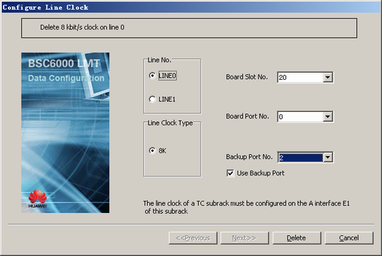
- Choose from the shortcut menu. A dialog box is displayed, as shown in Figure 1.
 NOTE:
NOTE: When the A interface E1 where the port of the selected Board Port No. is located incurs a fault, the GTCS cannot extract the line clock from the A interface. In this case, the GTCS can extract the line clock from the A interface through the A interface E1 where the port of the selected Backup Port No. is located.
- Board Slot No.: number of the slot where the GEIUA/GOIUA configured with the A interface E1 is located
- Board Port No.: number of the port connected to one A interface E1 on the GEIUA/GOIUA
- Backup Port No.: number of the port connected to another A interface E1 on the GEIUA
- Set the parameters by referring to Table 1.
- Click Add. The clock on LINE0 for the GTCS is configured.
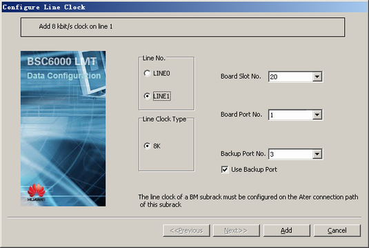
- Repeat 1 through 2 to open the configuration dialog box.
- Select LINE1 and set the parameters by referring to Table 2, as shown in Figure 2.
- Click Add. The clock on LINE1 for the GTCS is configured.
- Repeat 1 through 7 to configure the line clock for each GTCS.