This describes how to replace the BSC fan box. When the fan box is faulty, replace the fan box. The replacement of the fan box should be completed within one minute.
Prerequisites
- The tools required for replacing the board are ready. The tools are ESD wrist strap, cross screwdriver, and ESD box or bag.
- A spare fan box is ready and is configured based on field requirements.
Context
Wear an ESD wrist strap and connect it to the ESD connector on the cabinet before you perform the operation. For details, refer to Wearing an ESD Wrist Strap.
The heat dissipation of the system may be affected during the replacement of the fan box. If the replacement takes long, the boards in the cabinet may be damaged due to excessive temperature. Ensure that it takes within one minute to replace the fan box.
Procedure
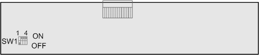
- According to the actual configuration of the fan box, set the DIP switch of the PFCU or set the jumper of the PFCB.
- Loosen the fastening screws on the panel of the fan box to be replaced.
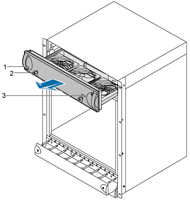
- Remove the fan box. Remove the fastening screws on the panel of the fan box. Hold the handle of the panel to remove the fan box along the guide rails (all the fans slow down and eventually stop). When the fan box is almost out of the cabinet,
hold the bottom of the fan box with one hand and the handle with the other hand until the fan box is pulled out of the cabinet. See Figure 3.
 CAUTION:
 When replacing a fan box, do not touch the inside of the fan box. The running fan or the metal edges of the mechanical parts may injure your fingers.
- Keep the replaced fan box for later handling.
- Mount the new fan box into the guide rails by holding the bottom of the fan box with one hand and the handle with the other hand. Push the fan box by holding the two handles of the fan box along the guide rails until the fans start to work.
- Fasten the screws on the panel of the fan box.
- After replacing the fan box, check the following items as listed in Table 3.
Table 3 Checklist for the fan box replacement Item
Result
Action
LEDs on the panel indicates the status of the fan box. For details about the LEDs, refer to LED on the fan box (Configuration PFCU)Table 1or LED on the fan box (Configuration PFCB)Table 1.
Normal
Go to the next item.
Abnormal
- Pull the fan box slightly out of the cabinet, adjust the position of the fan box, and then push the fan box in place. Check this item again.
- If the fault persists, contact Huawei Customer Service Center.
Alarms related to the fan box failure are cleared.
Cleared
End the check.
Not cleared
- To clear these alarms, refer to the alarm help information on the LMT.
- If the alarms persist, contact Huawei Customer Service Center.
- After cleaning the fan box, put it in an ESD box or bag.

Postrequisite
Contact the local Huawei office to dispose of the replaced fan box.