


Autodesk 3ds Max Tutorials > Materials and Mapping Tutorials > Vertex Color and Interactive Shading > Rendering to Texture >
Baking Scene Elements Into Textures
Examine the setup:
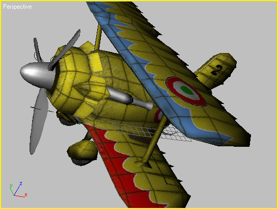
The scene consists of a texture-mapped biplane model and a single shadow-casting Omni light. First, you'll see how the scene looks rendered in 3ds Max.
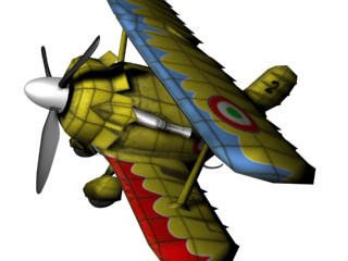
In the rendered image, note the presence of shadows, particularly those cast by the propeller blade and the vertical strut between the upper and lower wings. These shadows however, do not appear in the Perspective viewport.
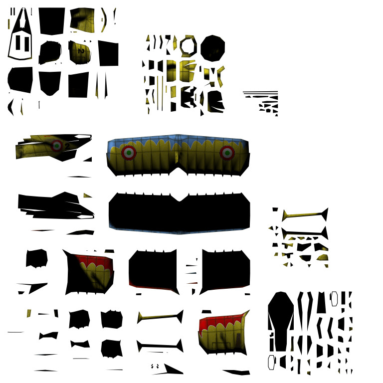
The Fuselage uses an Unwrap UVW modifier for complex and precise texture mapping. Because this is the only texture-mapped object in the scene, you'll concentrate on it for this lesson. First, you'll take a look at the texture.
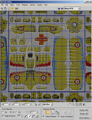
This opens the Edit UVWs dialog. You can see how the texture map is divided into various sections, with different face clusters overlaid on each. These face clusters are UVW mapping coordinates that correspond to different parts of the Fuselage mesh.
Bake the texture:
The Render To Textures dialog opens.
If you like, try selecting different objects in the Perspective viewport, and note that the Objects To Bake list updates dynamically. Finish by selecting only the Fuselage object.
This opens the Add Texture Elements dialog, with a list of different types of texture elements you can render. Typically, you want to combine all elements into a single texture, so you use CompleteMap.
CompleteMap appears in the Output rollout list, along with the default texture size to be generated: 256x 256. The original texture map is fairly large, so you'll probably want to render it to a bigger size.
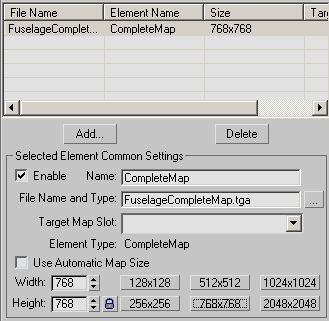
Other sizes are available from the preset buttons, and you can use the Size setting to specify any output size you want.
This size is lower than that of the original texture; using it will help you see the differences between it and the one that Render To Texture generates.
The name in the output list changes to reflect your edit, as does the File Name And Type entry.
Alerts appear briefly, displaying the progress of flattening UVs and baking the texture, then a virtual frame buffer window opens with the newly rendered CompleteMap texture. This image looks similar to what you saw in the Edit UVWs window, but the texture is subdivided differently.
Examine the results:
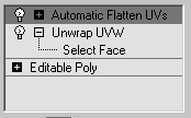
A second modifier, named Automatic Flatten UVs, has been added to the Fuselage. This is an Unwrap UVW modifier, but it was created and applied automatically by the Render To Texture function.
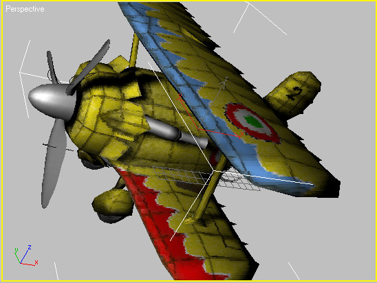
The Fuselage object is still mapped accurately, but the cast shadows now appear in the viewport. For example, if you move the light source, you can see that the shadows cast onto the fuselage from the propeller don't change with as the light source moves, because they're baked into the texture.
You can also see that the texture map as applied to the fuselage in the viewport is of lower quality, but if you render the image, the texture is of its original high quality. In the next few steps, you'll see why.
The software has renamed the material orig_Fuselage.
 Scroll
down to find an unused sample sphere, click it, then click the Get
Material button.
Scroll
down to find an unused sample sphere, click it, then click the Get
Material button.A single material now appears in the list. Its name is Fuselage (from the object it's applied to), and the type, Shell Material, appears next to the name. This material was generated automatically by Render To Texture, then applied to the Fuselage object.
Basically, a Shell material lets you combine two materials into one; you can see one material in the viewports while rendering with the other. When Render To Texture generates a Shell material, it uses the original material for rendering, and the baked material for displaying in the viewports.
You can find the scene to this point in tut_texturebake_finish.max.
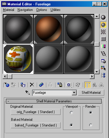
This material has only one rollout: Shell Material Parameters. It shows that the original material (orig_Fuselage) is to be rendered with, while the baked material (baked_Fuselage, generated by Render To Texture) is to be visible in the viewports.
 Click
the Original Material button, and then, on the Material Editor toolbar,
click the Show Map In Viewport button.
Click
the Original Material button, and then, on the Material Editor toolbar,
click the Show Map In Viewport button.This step lets you see the material in the viewport in the next step.
 Return
to the top level of the material, and on the Shell Material Parameters
rollout, under Viewport, click the top radio button (next to Original
Material).
Return
to the top level of the material, and on the Shell Material Parameters
rollout, under Viewport, click the top radio button (next to Original
Material).In the Perspective viewport, the Fuselage returns to its previous appearance, and the shadows go away.
The original shadows remain where you baked them. Depending on where you position the light source, you might see an additional set of shadows, cast by the light during the rendering.
Render other elements:
Besides the CompleteMap, you can render individual elements, one or more at a time.
The new material is unshaded, except where the shadows fall. You can use this type of texture if your target rendering engine supports compositing multiple textures.
Note that the rendered frame window still shows the CompleteMap, even though Render To Texture didn't save one. This is always the case, no matter which types of elements you render. You can turn off the automatic display of the frame window on the General Settings rollout.
They appear in that order in the list. With multiple textures in the list, you can specify output settings for each by clicking its list entry.
The Missing Map Targets dialog shows any texture elements that aren't assigned to target map slots.
The new Shell material is created for the first element in the list only, as shown in the Perspective viewport. However, all textures are saved in the target directory. You can see the LightingMap texture in the viewport by deleting the DiffuseMap.
Render To Texture generates a new material and applies it to the Fuselage, so it is now visible in the viewport. The LightingMap element includes all shading and shadows, but no diffuse coloring.
Render To Texture is a versatile tool that can save you time in generating texture maps for real-time applications. In this tutorial you learned how to bake different types of textures, and how to work with the Shell material that Render To Texture generates. Try generating other texture elements, then export them to your real-time 3D engine.