Autodesk 3ds Max Tutorials > Modeling Tutorials > Modeling a Low-Poly Character > Modeling a Low-Poly Head >
Creating the Helmet
In this lesson, you use part of your character's head to create a helmet. Then, you extend the geometry to define a rim and ear protectors.
Bevel the helmet:
 Go into
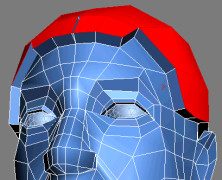
Polygon sub-object level and select the head's polygons between
the hair line and the base of the skull, excluding the ears.
Go into
Polygon sub-object level and select the head's polygons between
the hair line and the base of the skull, excluding the ears.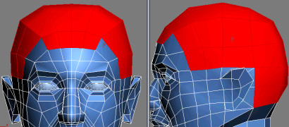
 Click
the light bulb icon next to the Symmetry modifier in the Modifier
Stack.
Click
the light bulb icon next to the Symmetry modifier in the Modifier
Stack.This turns the modifier off so you can clearly see one half of the object.
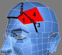
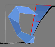
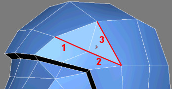
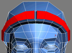
 Go into
Edge sub-object level and click the Bridge Settings button. On the
Bridge Edge dialog, choose Use Edge Selection and select the three
sets of border edges starting at the eyebrow. This leaves one face
open on the helmet. Set Segments to 2 and click
Apply when done.
Go into
Edge sub-object level and click the Bridge Settings button. On the
Bridge Edge dialog, choose Use Edge Selection and select the three
sets of border edges starting at the eyebrow. This leaves one face
open on the helmet. Set Segments to 2 and click
Apply when done.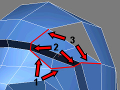
 Go into
Vertex sub-object level and adjust the helmet's vertices to match
the surrounding edge flow.
Go into
Vertex sub-object level and adjust the helmet's vertices to match
the surrounding edge flow.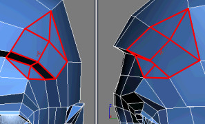
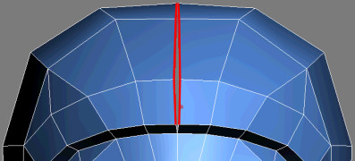
Click
the Symmetry light bulb to turn on the modifier.Notice the central gap in the helmet because of the middle vertices' offset on the X axis.
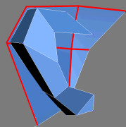
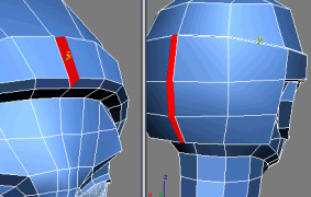
Bevel the helmet's rim:
Go into
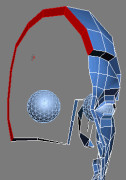
Polygon sub-object level and select the polygons shaping the helmet's
rim, as well the portion at the back of the head.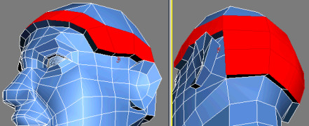
Go into
Vertex sub-object level and reset the respective vertices' X position
to unite both sides.Define the ear protector:
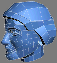
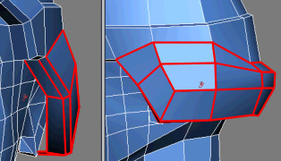
Go into
Polygon sub-object level, and then select the polygons surrounding
the ear.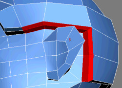
Go into
Edge sub-object level and click the Bridge Settings button.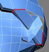
 Go into
Border sub-object level. Select the remaining border edge and click
Cap on the Edit Borders rollout.
Go into
Border sub-object level. Select the remaining border edge and click
Cap on the Edit Borders rollout.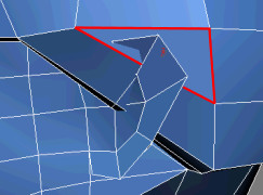
Go into
Vertex sub-object level and redistribute the vertices to better
cover the ear.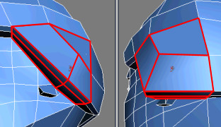
Go into
Edge sub-object level. Use the Cut or Connect tool to create a series
of edges at ear level. Connect these edges at the back of the helmet.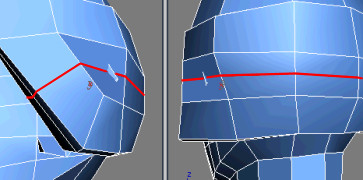
Taking it Further — Refining Inside the Ear Protectors
Use the tools and techniques learned in this lesson to create the inner part of the ear protectors. For example, you could use the Bridge tool to create new polygons from the current edge border, and then add some extra edges to bring the resulting vertices around the ears.
|
1. Use the Bridge and Cut tools to link edges together. |
|
2. Bridge the remaining edges. |
|
Adjust the vertices so the helmet doesn't obstruct the ears. |