


Using Unwrap UVW, Part 1
In this three-part lesson, you'll get an introduction to the Unwrap UVW modifier, and use several of its features.
All the files necessary for this tutorial are provided on the program disc in the \tutorials\materials_and_rendering directory. Before starting the tutorials, copy the \tutorials folder from the disc to your local program installation.
Examine the final mapping:
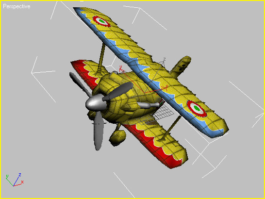
You'll start by looking at the final version of a fairly detailed object mapped with the Unwrap UVW modifier.
 Go to
the Modify panel and select the Fuselage object; just click a wing.
Go to
the Modify panel and select the Fuselage object; just click a wing.You can now see the object's modifier stack, with the Unwrap UVW modifier applied to the Editable Poly object.
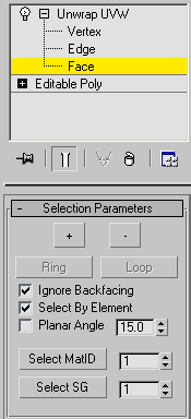
This will let you select large sections of the Fuselage object, rather than single faces.
This opens the Edit UVWs dialog, also known as the UVW editor.
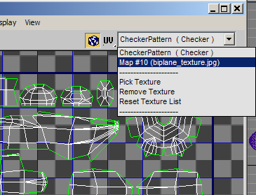
You can now see the UVW clusters laid out against the texture map in the background. Each cluster represents a section of the Fuselage geometry that is planar-mapped with the underlying area of the bitmap texture.
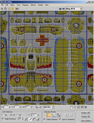
The entire wing is selected, and in the editor window, the UVW clusters assigned to it become highlighted.
Highlighting a cluster makes it easier to see how well its outline matches the shape of the underlying section of the texture map. To change the wireframe color used by the clusters, you can also use the Options button near the bottom-right corner of the Edit UVWs dialog. Also, it often helps to lower the bitmap brightness as well.
Most of the Fuselage parts are combined into a single element, which uses the clusters on the left side of the editor window.
The nose cone is mapped as a single piece, which is convenient to texture with a single area of the bitmap. It's not really flat, but the planar mapping works with it because of the UVW editor's ability to closely match the geometry with the bitmap on a per-vertex basis.
Because the housing structure is more complex than that of the nose cone, it makes sense to map it with four clusters instead of one.
Ultimately, it's up to you how you map your geometry; the UVW editor gives you the power and flexibility to use the method that works best for you.