


Using Unwrap UVW, Part 2
In this lesson, you'll examine Unwrap UVW's Flatten Mapping command for automatic mapping.
Use Flatten Mapping:
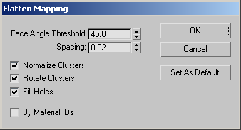
The Flatten Mapping dialog opens.
The software applies planar mapping to each section of the mesh based on the Flatten Mapping dialog settings. The editor now displays a very different set of UVW clusters. Each cluster consists of a set of contiguous faces in which the angle between neighboring faces is less than or equal to the Face Angle Threshold setting in the Flatten Mapping dialog.
The main difference is that there are many more clusters, and most of them are smaller than in the final. The wings are relatively flat, so their clusters are easy to identify, but most of the rest are not. You can remedy this somewhat by increasing the angle threshold.
Of course, the underlying texture map remains the same when you change the mapping. If you look at the Perspective viewport, you can see that the mapping is now much different than before.
The result is fewer clusters than before, but still many more than in the final. In the next procedure, you'll look at a couple of ways of combining these clusters.
Combine the UVW clusters:
You can use the editor's Stitch function to combine clusters one at a time, and the modifier's Planar Map command lets you combine several clusters simultaneously.
This causes all of the UVW clusters used by the nose-cone geometry to highlight in the editor.
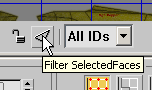
Now only the highlighted clusters appear.
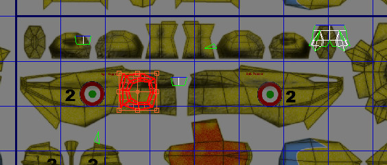
Highlighted edges and vertices appear on one or more other clusters to show the sub-objects shared with the selected cluster.
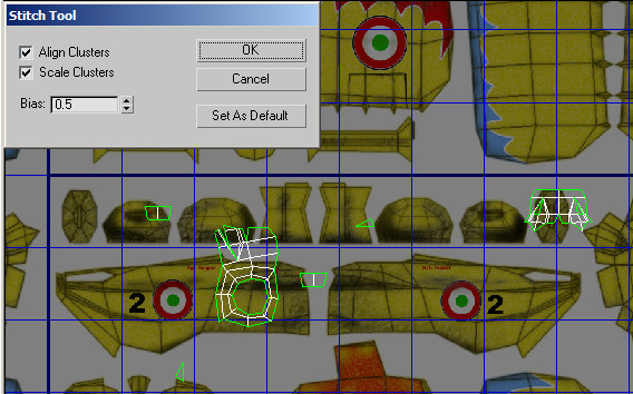
The Stitch Tool dialog appears, and one of the other clusters moves next to the selected clusters, with the shared sub-objects “stitched” together. The software automatically stitches the cluster with the most shared sub-objects; if two or more share the same number of sub-objects, it picks the one with the lowest vertex ID numbers. In this case, it picked the rightmost cluster near the top of the editor window.
When you turn off Align Clusters, the attached cluster moves back to its original position. Use this when the automatic alignment positions the attached cluster in an undesirable way, such as overlapping the first cluster.
Next, you'll use Planar Map to combine all of the nose cone clusters at once.
The Planar button turns yellow and the clusters combine into a single cluster that's roughly the shape of the nose-cone texture in the upper-right section of the bitmap. But the cluster is oriented differently than the texture, and is much bigger.
 Use
the Freeform Mode transform tools to fit the cluster to the nose-cone
texture. Drag the corners of the bounding box to scale the cluster,
and drag within the bounding box to move it. Check your work in
the viewport, and render if you like.
Use
the Freeform Mode transform tools to fit the cluster to the nose-cone
texture. Drag the corners of the bounding box to scale the cluster,
and drag within the bounding box to move it. Check your work in
the viewport, and render if you like.
To get an exact match, you'd have to move the vertices as well.
The Unwrap UVW modifier is a powerful tool for applying complex mapping to your objects. This tutorial covered a variety of methods for using the modifier, including how to coordinate selection of UVW coordinates and parts of the object, usage of the automatic mapping tools such as Flatten Mapping, combining mapping clusters, and sketching vertices.