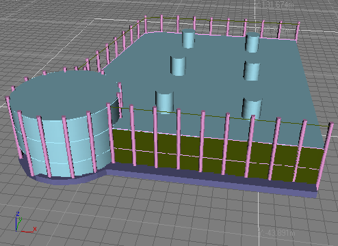
Creating the Main Building

Building an Architectural Model from a Concept Sketch

Creating the Second Building

Adding Glass and Columns
In this section you'll create lines to be used
as paths with the Spacing Tool. You'll then use the Spacing Tool
to create more columns around the building.
Set
up the lesson:
To start from this point:
- Continue
from the previous step, or open your saved file, mybuilding_nowalls.max.
- If
you want to start the lesson from here, choose File > Open, browse
to \tutorials\arch\, and open the building_nowalls.max file.
Use
the Spacing Tool to add columns:
- In
the Create panel > Shapes > Object Type rollout, click Line.
- In
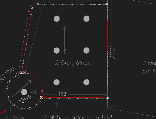
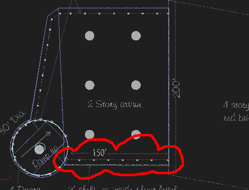
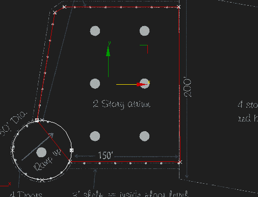
the Top viewport, create a line for the front wall.
- In
the Create panel > Name And Color rollout, enter Front
Wall Glass.
- In
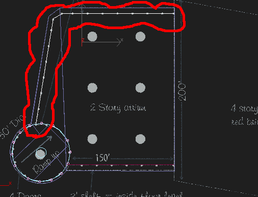
the Top viewport, create a second line for the left wall and rear
wall.
- In
the Create panel > Name And Color rollout, enter Rear
Wall Glass.
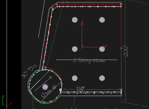
-
 In the
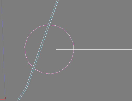
viewport navigation controls, click Region Zoom. Zoom in, centering
the region at the spot where the Front Wall Glass meets
the Rotunda.
 The illustration below gives you a rough idea
of how far to zoom in.
- When
the Display Background warning appears, click No.
- Right-click
twice in the viewport; once to turn off Region Zoom, and again to
exit the Line tool.
-
 On the
toolbar, click Select And Move.
 - Press
F3 to switch to Wireframe view.
- Click
the Front Wall Glass and move its
endpoint to the center of the nearest column.
TipYou
might not be able to move the line in two dimensions at first. Because
you're zoomed in, you can't use the Transform Gizmo. If you find
this is the case, right-click the blank area of the toolbar, and
display the Axis Constraints toolbar. Then on the Constraints toolbar,
click XY.
- Select
the column at the endpoint of the Front Wall Glass and
press Delete on your
keyboard.
-
 In the
viewport navigation controls, click Zoom Extents.
 - Press
F3 to revert to Shaded view.
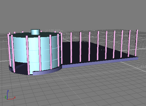
- Press H and select Thin Column 01 from
the list.
- On
the Tools menu choose the Spacing Tool.
- In
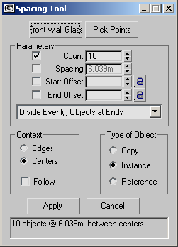
the Spacing Tool dialog, click the Pick Path button.
- Press H and select Front Wall Glass from
the list.
- In
the Spacing Tool dialog, set Count to 10. If you use
the keyboard, be sure to press the Tab or Enter key after typing the number
so the new value registers with the software.
- Click
Apply.
- In
the Spacing Tool dialog, click Pick Path.
- Press H and select Rear Wall Glass from
the list.
- In
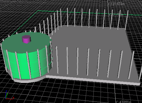
the Spacing Tool dialog, set Count to 18. If you use
the keyboard, be sure to press the Tab or Enter key after typing the number
so the new value registers with the software.
- Click
Apply.
- Close
the Spacing Tool dialog.
Attach
and clone the wall splines:
Next, you'll combine the two wall splines and
clone them, as you did with the rings around the rotunda, to create
horizontal steel beams.
- Press H and select Rear Wall Glass
from
the list.
- In
the Modify panel > Geometry rollout, click Attach.
- Press H and select Front Wall Glass from
the list.
- Click
the Attach button again to deactivate it.
- On
the menu bar, choose Edit > Clone.
- In
the Clone Options dialog > Object group, choose Copy.
- In
the Clone Options dialog > Name group, type Steel
Wall.
- Click
OK to close the dialog.
- On
the toolbar, click Select And Move if necessary.
- In
the status bar > Coordinate Display > Z field, enter 6.1m.
This moves the Steel Wall object
up 6.1 meters.
- In
the Modify panel > Rendering rollout, turn on the Enable in Renderer
check box, if it's not already on.
- In
the Rendering rollout, set the Thickness to 0.61m.
You can see the result of these settings when
you render your scene or by turning on Enable in Viewport.
Array
the wall splines:
- From
the Tools menu, choose Array.
- In
the Array dialog, click Reset All Parameters.
- In
the Array dialog, under Incremental, set the Move Z axis to 6.1m.
- In
the Type of Object group, choose Instance.
- In
the Array Dimensions group > 1D Count, enter 3.
- Click
OK to close the dialog.
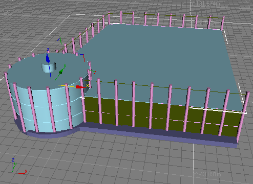
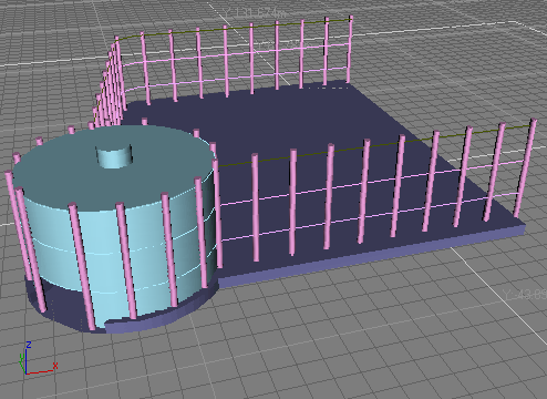
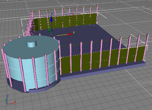
This creates the steel beams that will make
up the horizontal detail of the atrium.
Create
the walls:
Now you'll use Outline to give the wall some
thickness, and then extrude it.
- Press H and select Rear Wall Glass from
the list.
-
 In the
Modify panel > Selection rollout, click Spline to access this
sub-object level.
 - Press Ctrl+A to select both the splines.
- In
the Modify panel > Geometry rollout, enter −0.03m in the
Outline amount field.
You need not click the Outline button.
- In
the Modify panel > Selection rollout, click Spline to return
to object level.
- From
the Modifiers menu > Mesh Editing category, apply an Extrude
modifier. Set Amount to 12.2m.
- Press H and, in the following order, select Steel
Ring 02 and Steel Wall 01 from the list.
Tip
Ctrl adds
to a selection.
- On
the menu bar, choose Edit > Clone.
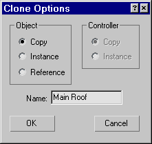
- In
the Clone Options dialog > Object group, choose Copy, name the
clone Main Roof, then click OK.
- Press H and select Main Roof from
the list.
Note that the objects were cloned separately,
and the Main Roof name was applied to
the cloned ring; the cloned wall object was automatically named Steel Wall
03.
Complete
the walls:
- From
the Modifiers menu > Patch/Spline Editing, click Edit Spline.
- In
the Modify panel > Geometry rollout, click Attach Mult.
- Select Steel
Wall 03 from the list and click Attach.
- In
the viewport, right-click and choose Hide Unselected.
-
 In the
Modify panel > Selection rollout, click Vertex.
 - In
the Modify panel > Geometry rollout, locate the Weld button,
then just below it, click the Connect button.
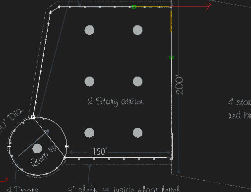
- Click
and drag to connect the adjacent endpoints of the splines that made
up the walls.
You'll be creating two splines: one across the
rotunda, and one on the right side of the building as viewed from
the top. The spline across the rotunda is necessary because you'll
be cutting the rotunda shape out of the building with Boolean, which
requires closed splines to work.
-
 In the
Modify panel > Selection rollout click Spline selection, then
select the spline that you just connected.
-
 In the
Modify panel > Geometry rollout, choose Boolean Subtraction.
 - Click
the Boolean button, and then in the Top viewport, select the Circle
shape.
The circle is subtracted from the building outline,
leaving an arc-shaped cutout.
- In
the Modify panel > Selection rollout, click Spline to return
to the object level.
- Apply
an Extrude modifier and set Amount to −0.15m.
- In
the viewport right-click and choose Unhide All.
Add
the six large columns:
You'll finish this lesson by using Array to
make six shorter copies of the Large Column object.
- Press H and select Large Column from
the list.
- On
the toolbar, choose Select and Move, if necessary.
- In
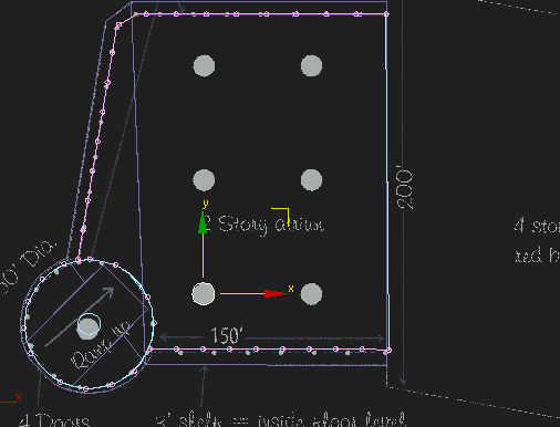
the Top viewport, hold down the Shift key
and move the Large Column over the lower-left
column of the sketch.
- In
the Clone Options dialog > Object group, click Copy, then click
OK.
- In
the Modify panel > Parameters rollout, set Amount to 18.0m.
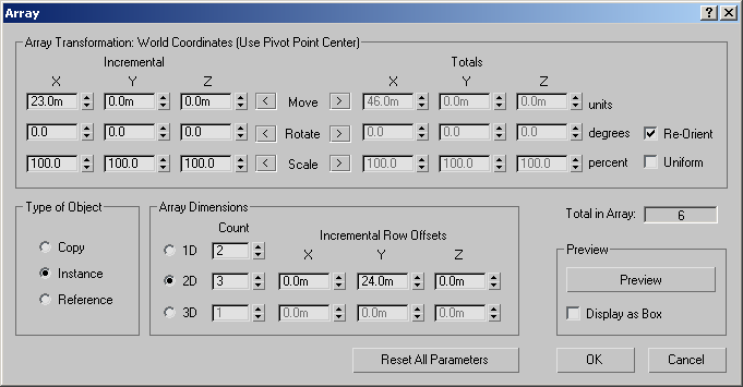
- Open
the Array dialog and click Reset All Parameters.
- In
the Array dialog, under Incremental, set X to 23.0m.
- In
the Type Of Object group, choose Instance.
- In
the Array Dimensions group, do the following:
- Click
2D and then set the 2D Count to 3.
- Under
Incremental Row Offsets, set Y to 24.0m.
- Click
OK to close the dialog.
This creates a two-dimensional array of six
columns, approximately where they're drawn in the sketch.
Save
your work:
- On
the menu bar, choose File > Save As. Name the file mybuilding.max.
 In the
viewport navigation controls, click Region Zoom. Zoom in, centering
the region at the spot where the Front Wall Glass meets
the Rotunda.
  On the
toolbar, click Select And Move.
 In the
viewport navigation controls, click Zoom Extents.
 In the
Modify panel > Selection rollout, click Spline to access this
sub-object level.
 In the
Modify panel > Selection rollout, click Vertex.
 In the
Modify panel > Selection rollout click Spline selection, then
select the spline that you just connected.
 In the
Modify panel > Geometry rollout, choose Boolean Subtraction.