Incorporating the Sketch

Building an Architectural Model from a Concept Sketch

Creating the Main Building

Creating the Building
You will begin creating the building, starting
with the main entrance rotunda. Because you are not building this
to scale, disregard the dimensions on the sketch.
Set
up the lesson:
- Continue
from the previous step, or open the tutorial file modelfromsketch_02.max from the \tutorials\arch directory.
NoteIf you do open the provided file, the viewport
background will not be visible in the Top viewport. To display the
viewport background, activate the Top viewport and choose Views
> Viewport Background. In the Background Source group click Files,
and then navigate, if necessary, to the \tutorials\arch folder
and highlight sketch.gif.
Start
the main entrance rotunda:
-
 In the
viewport navigation tools, click Zoom Region.
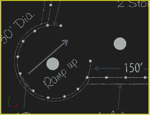
 - In
the Top view, drag a rectangle to zoom in on the main entrance in
the lower left of the sketch.
NoteIf
you zoom in too far, a dialog will appear indicating that the amount
of RAM needed to display the background image may exceed the available
amount. Answer NO to the warning. To display your viewport after you’ve
answered NO to the warning, right-click the viewport label and choose
Show Background.
-
 On the
Create panel, choose Shapes.
On the
Create panel, choose Shapes.The default Shapes category is Splines, which
are line-based shapes you can use as the basis of 3D objects.
-
 On the
Object Type rollout, click Circle.
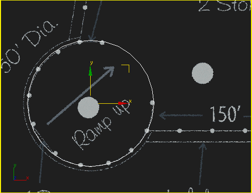
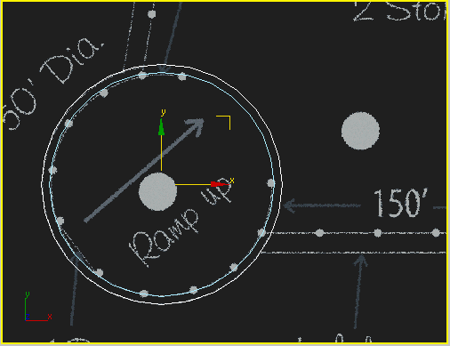
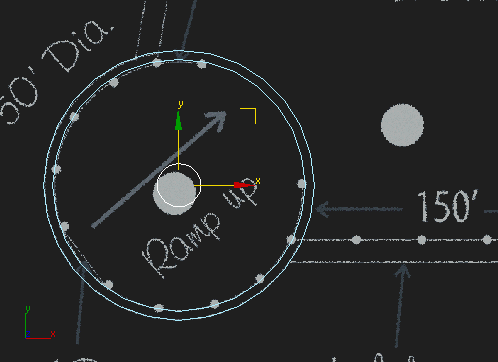
 - In
the Top viewport, position the mouse cursor in the center of the
rotunda, and then click and drag outward to draw a circle that lines up
with the glass walls of the rotunda. If necessary, right-click and
choose Move, then move the circle into place.
TipTo
move the circle, drag the circle itself, the X or Y arrow, or the yellow
corner box where the arrows meet.
- On
the menu bar, choose Edit > Clone.
- In
the Clone Options dialog,
make sure Copy is chosen, enter
the name Steel Ring 01, and then click
OK to make a copy of Circle01.
A new copy of the circle is created on top of
the original circle.
- Press H to open the Select From Scene
dialog, choose Circle01 in the Name column, and click OK.
- From
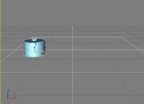
the Modifiers menu > Mesh Editing category, apply an Extrude
modifier. On the Modify panel > Parameters rollout, set Amount to 18.3m.
- Click
in a viewport, press H,
select the Steel Ring 01 object, and click
OK.
By default, unmodified splines don't render
and appear as wireframe objects in all viewports, shaded or not.
The spline Rendering settings let splines appear as “solid” mesh
objects in the viewports, when rendered, or both.
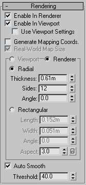
- On
the Modify panel > Rendering rollout, turn on both Enable In
Renderer and Enable In Viewport.
The spline now has thickness in the viewport
and will be visible when rendered.
- Set
Thickness to 0.61m.
This parameter determines the thickness of the
spline when rendered.
-
 On the
toolbar, click Select And Move.
 - In
the status bar (bottom of the screen) > coordinate display >
Z field, enter 6.1m.
This moves the ring up 6.1 meters.
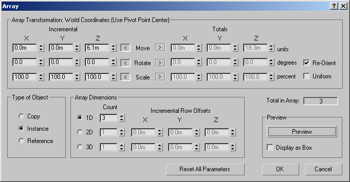
- From
the Tools menu choose Array.
- In
the Array dialog, under Incremental, set the Move Z axis to 6.1m.
- In
the Type Of Object group, choose Instance.
- In
the Array Dimensions group > 1D Count, enter 3.
- Click
OK.
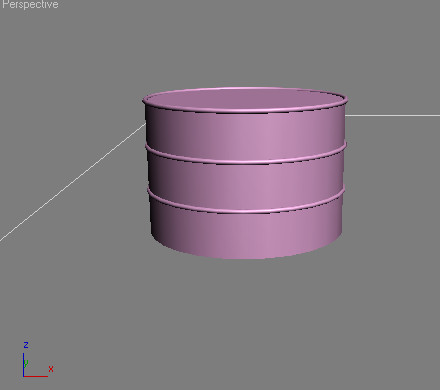
This closes the dialog and creates two additional
steel holding rings around the glass rotunda.
Add
the outer wall and central column:
You'll now use the rotunda circle to create
an outer wall.
- Select
the Circle01 object.
- From
the Edit menu, choose Clone.
- In
the Clone Options dialog > Object group, choose Copy.
- Click
OK to make a copy of Circle01.
-
 In the
Modify panel, under the modifier stack display, click Remove Modifier.
 - In
the Modify panel > Parameters rollout, change the Radius amount
to match the outer circle in the sketch (about 15.0m).
- On
the menu bar, choose Edit > Clone.
- In
the Clone Options dialog > Name group, type Large
Column. Make sure the active choice is still Copy, then
click OK.
- In
the Modify panel > Parameters rollout, change
the Radius amount to 2.4m to match the small solid
circle in the sketch.
You needn't move the column to match the sketch.
Remember, this is just a rough sketch, not a precise design.
- Apply
an Extrude modifier and set Amount to 21.3m.
- Press H and select Circle01 from the list.
- At
the top of the Modify panel, rename Circle01 to Rotunda
Glass.
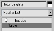
- In
the modifier stack display, choose Circle.
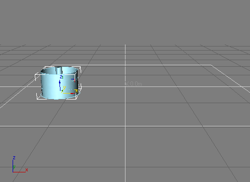
 If you
can no longer see the extrusion, it is because you've moved "down"
the stack to the original shape. In order to see "up" the stack,
you must turn on Show End Result. If this is already on you will
see the extrusion without problem.
- From
the Modifier List > Object Space Modifiers category, choose Edit
Spline.
Like other object types in 3ds Max, the spline
has sub-objects you can edit independently, such as Vertex and Segment,
and you can also edit (transform) the entire object at the top level:
Spline. A spline object can comprise several splines (separate curves),
so it also has a Spline sub-object level so you can edit a single
constituent spline.
-
 On the
Modify panel > Selection rollout, click the Spline button.
 This places you at the Spline sub-object level,
which is the only one that affords access to the Outline function.
- In
the Modify panel > Geometry rollout, next to the Outline button,
enter 0.03m.
This creates a nested shape, like the letter
O. Notice that the outline field returns to the original 0.0 value
after you create the outline. This is because Outline is an action,
rather than a parameter.
- In
the Modify panel > Selection rollout, click Spline to exit the sub-object
level.
- In
the modifier stack display, choose Circle. When the warning appears,
click Yes to continue.
You can now see the result of outlining the
spline: Instead of a solid column, you have a thin, circular wall.
Create
doorways with Boolean:
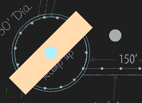
Next, you'll create a box and then use Boolean
to subtract its shape from the rotunda.
-
 In the
Create panel > Geometry > Standard Primitives > Object
Type rollout, click Box.
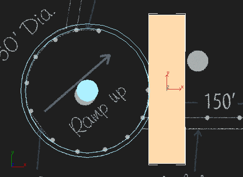
 - In
the Top viewport, click and drag out a box as shown in the following
illustration.
TipRight-click
the Top viewport label and change the viewport to Smooth+Highlights.
- In
the Modify panel > Parameters rollout, change the Length amount
to 9.0m, the Width to 36.5m,
and the Height to 6.0m.
-
 On the
toolbar, click Align.
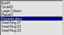
 - Press H, choose Rotunda Glass from the
list, and then click Pick.
- In
the Align Selection dialog > Align Position group, turn on X Position
and Y Position.
- Click
OK to close the dialog.
-
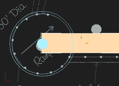
 On the
toolbar, click Select And Rotate.
 - In
the Coordinate Display > Z field, enter 45.0.
This rotates the box into the same position
and orientation as the rotunda openings in the plan.
- Select
the Rotunda Glass object.
- Go
to the Create panel, and from the drop-down category list, choose
Compound Objects.
- On
the Object Type rollout, click Boolean.
- On
the Parameters rollout, make sure the Subtraction (A-B) item is
active.
- On
the Pick Boolean rollout, click Pick Operand B, and then click the
box.
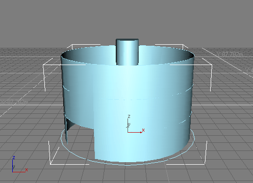
The box is subtracted from the rotunda object,
leaving two open doorways.
- Right-click
in the viewport to exit the Boolean operation.
Create
the roof:
Here you'll clone the topmost ring and then
extrude the clone, producing a roof.
- Press H and select Steel Ring 03 from
the list.
This is the topmost ring.
- From
the Edit menu, choose Clone.
- Name
the clone Roof, click Instance, and then
click OK.
NoteAn
instance derives certain characteristics from the object it's copied
from, so changing one also alters the other.
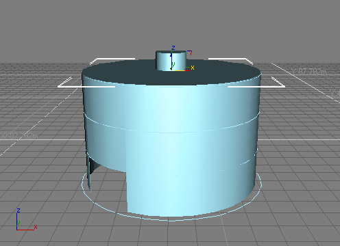
- On
the Modify panel, add an Extrude modifier.
The roof appears at the top of the rotunda.
- On
the Modify panel > Parameters rollout, set the Amount to 0.15m.
This gives the roof the appropriate thickness.
Creating the Outer Columns
In the next few steps, you will create columns
from cylinders and make multiple copies using Array.
Create
columns using the cylinder object:
- In
the Create panel > Geometry drop-down list, choose Standard Primitives.
-
 In the
Create panel > Object Type rollout, click Cylinder.
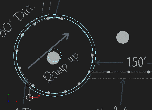
 - In
the Top viewport, create a cylinder near the entrance opening in
the lower left of the rotunda.
- In
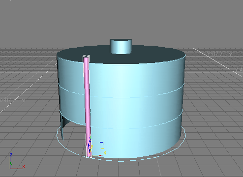
the Parameters rollout, change Radius to 0.5m and Height
to 19.5m.
-
 On the
toolbar, click Select and Move.
 - In
the Coordinate Display > X field, enter -57.037m, set
Y to −32.79m, and make sure Z is set
to 0.0m.
The cylinder lines up with the right side of
the opening in the Rotunda Glass object, with the
Rotunda Glass passing through the center of the cylinder.
- In
the Modify panel, rename the cylinder to Thin Column 01.
- In
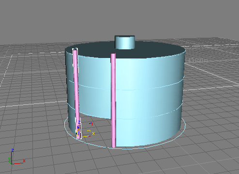
the Perspective viewport, hold the Shift key
and move the Thin Column 01 cylinder so it lines up with the left
side of the opening in the Rotunda Glass, with the Rotunda Glass
passing through the center of the cylinder.
NoteTransforming
an object while pressing Shift causes
the object to be copied before it is moved.
- When
the Clone Options dialog appears, choose Instance, and then click
OK.
- In
the status bar > Coordinate Display > X field, enter -63.4m,
set Y to −26.52m, and make sure Z is set
to 0.0m.
Create
an array of columns:
Next, you'll create a circular array of thin
columns with the large column as the center.
-
 On the
toolbar, choose Select And Rotate, then click the Reference Coordinate
System drop-down to the right and choose Pick from the list.
- In
a viewport, select the Large Column object.
The name of the object appears in the Reference
Coordinate System field.
-
 On the
toolbar, from the Use Center flyout, choose Use Transform Coordinate
Center.
 This tells 3ds Max to use the Large
Column object as the center point for the cylinders to
rotate around in the array.
- Press H and select Thin Column 01 from
the list.
- Right-click
in the Top viewport to make it active.
- From
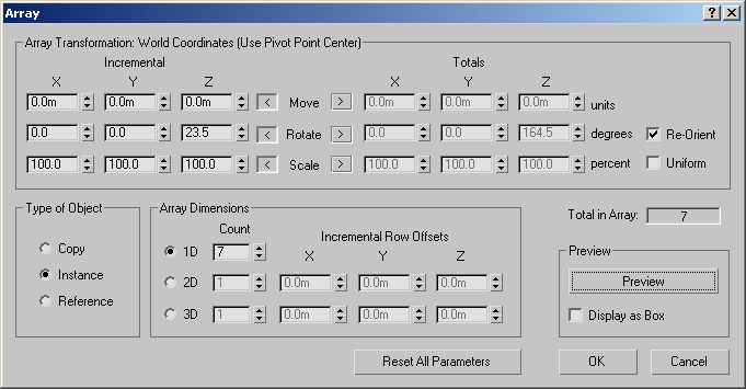
the Tools menu, choose Array.
- In
the Array dialog, click Reset All Parameters.
- In
the Array Transformation group, under Incremental, set the Rotate
Z axis amount to 23.5 degrees.
- In
the Array dialog > Type of Object group, click Instance.
- In
the Array dialog > Array Dimensions group, enter a 1D Count of 7.
Using instances lets you change all the columns
by editing only one.
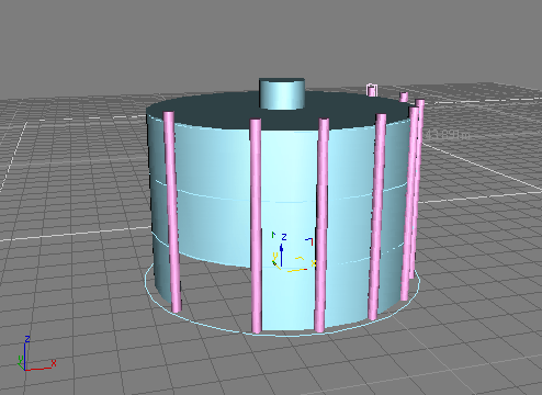
- Click
OK to close the Array dialog.
A semicircular array of columns appears on one
side of the rotunda.
- Press H and select Thin Column 02from
the list.
- From
the Tools menu, choose Array.
You'll create the same number of instances on
the other side, so you need change only one setting.
- In
the Array Transformation group, under Incremental, set the Rotate
Z axis amount to -23.5 degrees.
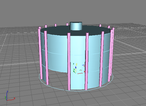
- Click
OK to close the Array dialog.
A semicircular array of columns appears on the
other side of the rotunda.
Save
your work:
- On
the menu bar, choose File > Save As. Name your scene myrotunda.max.
 In the
viewport navigation tools, click Zoom Region.
 On the
Create panel, choose Shapes.
 On the
Object Type rollout, click Circle.
 On the
toolbar, click Select And Move.
 In the
Modify panel, under the modifier stack display, click Remove Modifier.
 If you
can no longer see the extrusion, it is because you've moved "down"
the stack to the original shape. In order to see "up" the stack,
you must turn on Show End Result. If this is already on you will
see the extrusion without problem.
 On the
Modify panel > Selection rollout, click the Spline button.
 In the
Create panel > Geometry > Standard Primitives > Object
Type rollout, click Box.
 On the
toolbar, click Align.

 On the
toolbar, click Select And Rotate.
 In the
Create panel > Object Type rollout, click Cylinder.
 On the
toolbar, click Select and Move.
 On the
toolbar, choose Select And Rotate, then click the Reference Coordinate
System drop-down to the right and choose Pick from the list.
 On the
toolbar, from the Use Center flyout, choose Use Transform Coordinate
Center.