This describes how to configure the connection path between the GTCS and the GMPS/GEPS on the Ater interface.
| Scenario | BSC initial configuration and BSC capacity expansion |
| Mandatory/Optional | Mandatory |
When the GTCS is configured on the MSC side, the GMPS can be connected only to the main GTCS. The GEPS does not have this restriction.
The Ater connection path is established between GEIUTs or between GOIUTs. You can specify different ports to configure more than one Ater connection path between interface boards.
You can configure a maximum of 32 GEIUTs and a maximum of 32 GOIUTs. The maximum number of Ater connection paths, which depends on system specifications, is 128 in a BSC.
Prerequisites
- The subracks between which the Ater connection path is to be established are configured and the relation between the GMPS/GEPS and OSP is configured. For details, see Configuring the Subrack-OPC Mapping.
- The GEIUT/GOIUT in the two subracks between which the Ater connection path is to be established is configured. For details, see Configuring the GEIUT/GOIUT.
Preparation
Parameter |
Example |
Source |
|---|---|---|
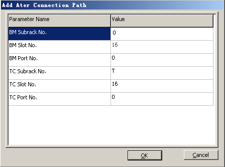
BM Subrack No. |
0 |
BSC internal planning |
BM Slot No. |
16 |
BSC internal planning |
BM Port No. |
0 |
BSC internal planning |
TC Subrack No. |
7 |
BSC internal planning |
TC Slot No. |
16 |
BSC internal planning |
TC Port No. |
0 |
BSC internal planning |
Parameter |
Example |
Source |
|---|---|---|
BM Subrack No. |
1 |
BSC internal planning |
BM Slot No. |
16 |
BSC internal planning |
BM Port No. |
0 |
BSC internal planning |
TC Subrack No. |
7 |
BSC internal planning |
TC Slot No. |
16 |
BSC internal planning |
TC Port No. |
0 |
BSC internal planning |
The following procedure takes how to configure the Ater connection path between the GMPS and the GTCS as an example.
On the LMT, the GMPS and the GEPS are collectively known as the BM subrack. They are identified by different subrack numbers.
Procedure
- On the BSC6000 Local Maintenance Terminal, right-click the GEIUT in the GMPS.
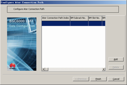
- Choose from the shortcut menu. A dialog box is displayed, as shown in Figure 1.
- Click Add. A dialog box is displayed, as shown in Figure 2.
- Set the parameters by referring to Table 1.
- Click OK to return to the dialog box, as shown in Figure 1.
- Click Finish. The configuration of the Ater connection path between the GMPS and the GTCS is complete.
- Repeat 1 through 6 to add multiple Ater connection paths between the GMPS and the GTCS.