This describes how to configure the line clock for the GMPS. The GMPS extracts the line clock from the GTCS through the Ater interface. This line clock is used as the input clock for the GGCU in the GMPS.
| Scenario | BSC initial configuration and BSC capacity expansion |
| Mandatory/Optional | Optional |
On the GEIUT, up to two line clocks can be configured on the Ater connection paths of the GMPS. A line clock maps an Ater connection path. On the GOIUT, only one line clock can be configured on port 0.
Prerequisites
- The GEIUT/GOIUT in the GMPS is configured. For details, see Configuring the GEIUT/GOIUT.
- The GGCU in the GMPS is configured. For details, see Configuring the GGCU.
- If the line clock is to be configured on the GEIUT, the Ater connection path in the GMPS must be configured. For details, see Configuring the Ater Connection Path.
Preparation
The following procedure takes how to configure two line clock signals on the GEIUT in the GMPS as an example.
Parameter |
Example |
Source |
|---|---|---|
Line No. |
LINE0 |
BSC internal planning |
Line Clock Type |
8K |
BSC internal planning |
Board Slot No. |
16 |
BSC internal planning |
Board Port No. |
0 |
BSC internal planning |
Backup Port No. |
2 |
BSC internal planning |
Parameter |
Example |
Source |
|---|---|---|
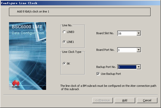
Line No. |
LINE1 |
BSC internal planning |
Line Clock Type |
8K |
BSC internal planning |
Board Slot No. |
16 |
BSC internal planning |
Board Port No. |
1 |
BSC internal planning |
Backup Port No. |
3 |
BSC internal planning |
Procedure
- On the BSC6000 Local Maintenance Terminal, right-click the edge of the GMPS.
- Choose from the shortcut menu. A dialog box is displayed, as shown in Figure 1.
 NOTE:
NOTE: If the Ater connection path where the port of the selected Board Port No. is located incurs a fault, the GMPS cannot extract the line clock from the Ater interface. In this case, the GMPS can extract the line clock from the Ater interface through the Ater connection path where the port of the selected Backup Port No. is located.
- Board Slot No.: number of the slot where the GEIUT/GOIUT configured with the Ater connection path is located
- Board Port No.: number of the port connected to one Ater connection path on the GEIUT/GOIUT
- Backup Port No.: number of the port connected to another Ater connection path on the GEIUT
- Set the parameters by referring to Table 1.
- Click Add. The clock on LINE0 for the GMPS is configured.
- Repeat 1 through 2 to open the configuration dialog box.
- Select LINE1 and set the parameters by referring to Table 2, as shown in Figure 2.
- Click Add. The clock on LINE1 for the GMPS is configured.