Autodesk 3ds Max Tutorials > Modeling Tutorials > Modeling a Low-Poly Character > Modeling a Low-Poly Body >
Creating the Boots
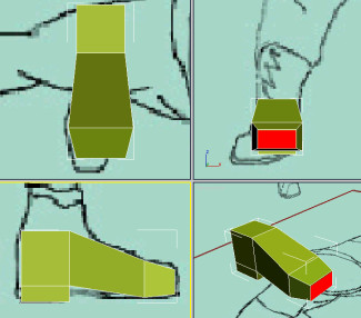
In this lesson, you create the boots of the helicopter pilot by using a simple box primitive. You then convert the box to editable poly format and start sculpting the boot using sub-objects such as vertex, edge and polygon.
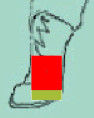
Create a box primitive:
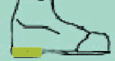
 On the
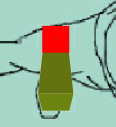
Modify panel, click the Polygon button.
On the
Modify panel, click the Polygon button.The top polygon on the box highlights in red.
 Alternatively,
you can lock the selection by clicking the Lock Selection toggle
on the status bar.
Alternatively,
you can lock the selection by clicking the Lock Selection toggle
on the status bar.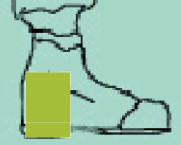
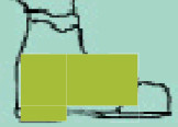

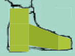
The bulk of the work is done, but you still need to refine the boot to make it look better.
Refine the boot:
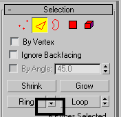
 On the
Selection rollout, click Edge.
On the
Selection rollout, click Edge.
All edges around the foot are selected.
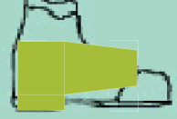
This creates an extra division running horizontally through the previously selected edges.
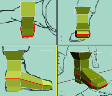
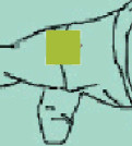
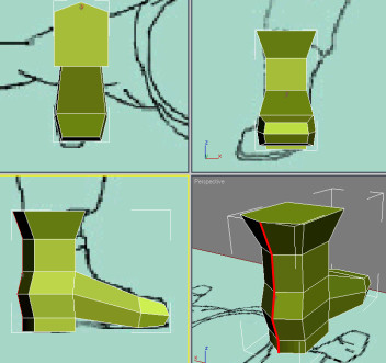
 In the
Perspective viewport, use Arc Rotate SubObject to view the back
of the boot.
In the
Perspective viewport, use Arc Rotate SubObject to view the back
of the boot.
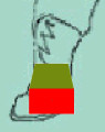
A new vertical division goes through the previously selected edges.
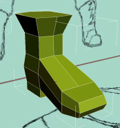
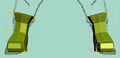
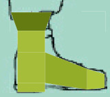
Finalize the boot:
Mirror the boot:
 On the
main toolbar, activate the Mirror tool.
On the
main toolbar, activate the Mirror tool.