Working with Biped Parts

Adjusting the Biped to the Model

Applying the Physique Modifier

Aligning the Biped to the Model
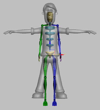
In this lesson, you'll pose a biped to fit a specific
character by moving, rotating, and scaling biped parts.
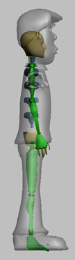
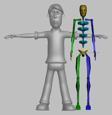
When correctly posed, the biped's torso, arms,
and legs fit just inside the mesh. Fingers and toes extend just
beyond the mesh to make skinning easier later on.
When posing the biped, Figure mode must be turned
on. This mode tells 3ds Max that you are posing the biped rather
than animating it.
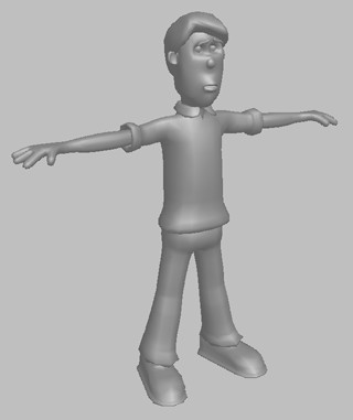
The character you’ll use in this lesson has
a human form, and will not require a tail, ponytails, or props
Set
up for this lesson:
- Load
the file align_wilson_start.max.
This scene
contains a model of a man named Wilson.
- Inspect
the model to see the number of fingers and toes. This model has
three fingers and a thumb, and the fingers are short. Wilson is wearing
shoes, so no toes are visible.
Prepare
the model:
Your work with the biped will be much easier
if you make a selection set for the model, make it see-through,
and freeze it.
- Select
the entire model.
- In
the Named Selection Sets entry area on the Main toolbar, enter the
name Wilson Mesh.
- On
the Display panel > Display Properties rollout, turn on See-Through.
The model
turns gray and becomes see-through. Making the model see-through
will allow you to see the biped as you pose it inside the model.
- On
the Display panel > Display Properties rollout, turn off Show Frozen
in Gray.
This lets the model retain a little of its shading
when frozen.
- On
the Display panel > Freeze rollout, click Freeze Selected.
You freeze
the model so you won’t accidentally select it while working with
the biped.
Create
a biped:
- Choose
Create panel > Systems > Biped.
- Click
near Wilson’s feet in the Front viewport and drag upward to create
a biped about the same size as the model.
Because
Wilson is wearing shoes, there's no reason to have separate toes.
You'll give the biped just one toe with one link, which will control
the entire ball and toe of the shoe.
- Near
the bottom of the Create Biped rollout, change Toes to 1 and
Toe Links to 1.
When you
inspected the model earlier, you found that Wilson has three fingers
and a thumb for a total of four fingers. The fingers are short,
so only two finger links are needed.
- Set
Fingers to 4 and Finger Links to 2.
Wilson's
neck is rather stubby, so he needs only one neck link.
- Set
Neck Links to 1.
Position
the biped:
-
 Open
the Motion panel.
Open
the Motion panel. -
 In the
Biped rollout, click Figure mode to turn it on.
In the
Biped rollout, click Figure mode to turn it on.If the
Biped rollout doesn’t appear on the Motion panel, select any part
of the biped to make it appear.
ImportantBe
sure to turn on Figure mode before continuing. Figure mode will
retain the pose you are about to create.
- Select
the center of mass (COM), the blue tetrahedron at the center of
the biped’s pelvis.
- In
the Front viewport, move the COM to the center of the model’s hips.
- Check
in all viewports and move the COM as necessary to put it inside
the character’s hips.
Pose
the legs:
- Select
both the upper and lower parts of both legs.
- In
the Front viewport, scale both legs so the bottoms of the biped’s
feet align with the model’s feet.
- Select
both thighs. Rotate the thighs to make the biped's legs parallel
to the mesh legs.
The goal
is to make the biped's legs go down the centers of the mesh legs,
but you can't do it until you scale the pelvis.
- Select
the biped’s pelvis, the orange triangle around the COM.
- Scale
the pelvis on its local Z-axis so the biped legs go down the centers
of the mesh legs.
You might
need to rotate the legs again, and scale the pelvis again. Work
back and forth between scaling the pelvis and rotating the legs
until the legs go straight down the middle of the mesh legs.
Scale
the legs:
- In
the Left viewport, right-click the viewport label and turn on Edged
Faces so you can see the knee detail on the pant legs.
- Scale
and rotate the thighs so the knee joint falls at the center of the
knee detail on the pants.
So far
you have been posing both legs at the same time. It is possible
to pose one leg or arm first, then copy and paste it to the other side.
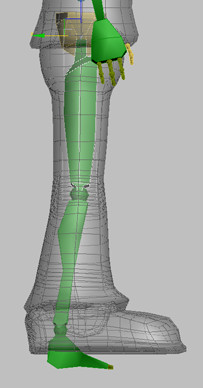
- In
the Front viewport, select one calf. Scale the calf so the ankle joint
falls just above the bottom of the pant leg.
- Scale
the foot so its bottom reaches the bottom of the mesh foot.
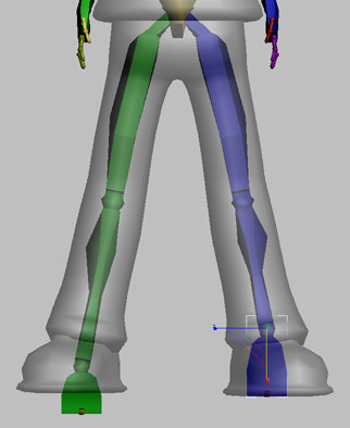
- Select
both the foot and calf you just scaled.
-
 In the
Copy/Paste rollout, turn on Posture. Click Copy Posture.
In the
Copy/Paste rollout, turn on Posture. Click Copy Posture. -
 Click
Paste Posture Opposite.
Click
Paste Posture Opposite.
Now the
two legs match.
- In
the Left viewport, check to see if the ankle joint meets the bottom
of the leg. If not, change the Ankle Attach parameter on the Structure
rollout to 0.2 or 0.25 to make
the ankle match the leg.
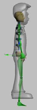
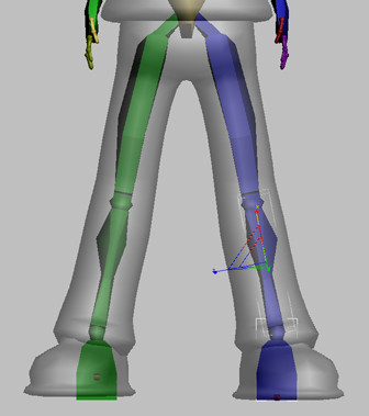
- In
the Left viewport, rotate the thighs, calves and feet so they align
as well as possible with the model.
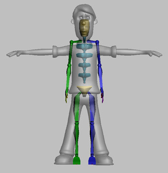
The file align_wilson_legs.max contains
the biped posed up to this point.
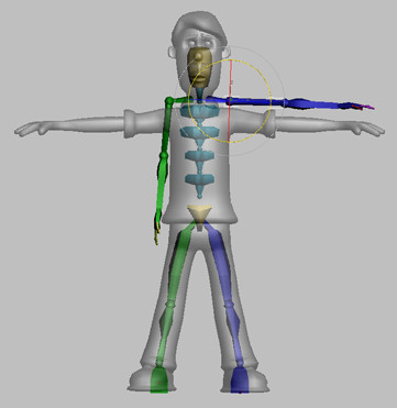
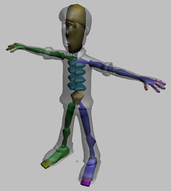
Position
the arms and spine:
- Select
one of the biped’s upper arms.
- In
the Front viewport, rotate the upper arm upward to make the arm
parallel with the model’s arm. Don’t be concerned with fitting the arm
at this time; simply make it parallel.
- Select
all the spine links and make a selection set called Biped
Spine.
- In
the Front viewport, scale the spine upward or downward to make the
upper arm fall into place.
-
Select
the posed upper arm. In the Copy/Paste rollout, copy and paste this
pose to the other side of the biped using Copy Posture and Paste
Posture Opposite.
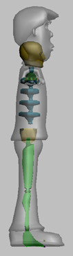
- Use
the Biped Spine selection set to select the spine links. In the Left
viewport, rotate the spine links slightly so they follow the curvature of
the spine. You might need to move the lowest spine link to align
the spine correctly.
ImportantDon't
rotate the COM when posing the biped. Instead, move the lowest spine
link to adjust the position of the spine and upper body.
Now that
the spine is curved correctly, the arms might be out of place again.
- Use
the named selection set to select the entire spine. In the Front
viewport, scale the spine again to make the arms fall into place.
- Check
the spine again in the Left viewport to ensure it still follows
the shape of the character’s torso.
As with
the legs and pelvis, you have to work back and forth between the
spine and the arms to make both fall correctly inside the mesh.
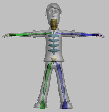
- In
the Front and Left viewports, scale the widths of the spine bones
to make them fit the mesh more closely.
Make each
spine bone about two-thirds the size of the mesh. You will have
to scale some spine bones more than others.
Pose
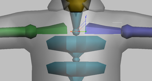
the arms:
The posing of the arm starts with the clavicle
bone, which connects the arm to the torso. Proper scaling of this
bone leads to easier skinning of the underarm and shoulder areas
later on.
- Select
one clavicle. In the Front viewport, scale the clavicle slightly
along its X-axis so the biped's shoulder joint falls in the center
of the mesh shoulder.
- In
Top viewport, work with the upper and lower portions of the same
arm. Scale and rotate the arm bones as necessary to fit it to the
mesh, taking care to align the biped’s elbow and wrist joints with
the same joints on the mesh.
TipYou can move quickly between parent and
child bones by pressing Page
Up and Page Down on
the keyboard.
- In
the Front viewport, rotate the arm if necessary to make it go down
the center of the mesh.
- Select
the clavicle, upper arm, and lower arm, and copy and paste the pose
to the opposite side of the biped.
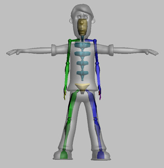
The file align_wilson_arms.max contains the
biped posed up to this point.
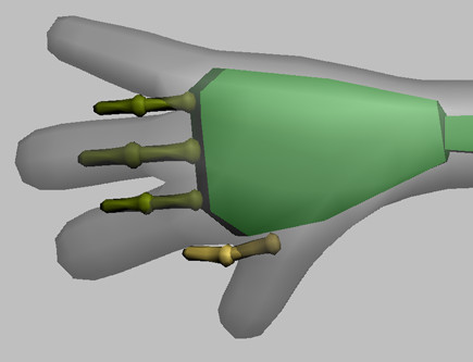
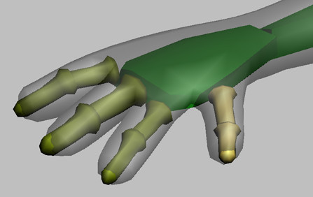
Pose
the hands:
Positioning the fingers is the most challenging
part of posing the biped. Each finger joint must be moved and rotated
separately.
You can rotate each finger and thumb joint,
but you can move only the base of each finger and thumb.
You’ll have an easier time posing the fingers
if you work with the bases of fingers first, moving each one into
place before rotating and scaling the finger joints.
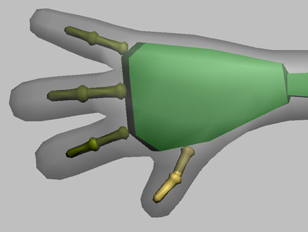
- In
Top, Front, and User viewports, zoom in on one of the hands.
- In
the Top viewport, rotate the hand slightly if necessary to make
it fit the mesh better.
- Scale
the biped hand so the palm nearly reaches the point where the pinky
finger starts.
- Check
the hand in the Left viewport, and if necessary, rotate it to fit
the center of the mesh hand.
- In
the Top viewport, move the base of the thumb and each finger to
match the base of the corresponding digit on the mesh. Don’t concern
yourself with the rotation of the fingers just yet.
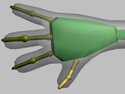
- Rotate
base of each finger and the thumb so each goes up the length of
the corresponding mesh finger. You might find you have to move the
base of the finger again to make it align correctly.
- Scale
the lengths of the finger joints so the first goes about halfway
down the finger, and the last extends just beyond the mesh fingertip. This
will help later on when skinning the character.
- Using
the Top and Front viewports, scale the width and height of each
biped finger to about two-thirds the size of the corresponding mesh
finger.
- In
the User view, rotate the finger joints to fit the fingers. You can
also move each finger base up or down to improve the fit. Look at
the hand from various angles to check the fit.
Tip To
rotate the view around the hand, select one or more finger bones
and use Arc Rotate Selected in the User viewport.
There is
no shortcut to posing the hand correctly. You must look at the hand
carefully from all angles to ensure the bones are centered down
the mesh fingers and thumb. The thumb bones can be challenging to
pose because they rotate differently from the fingers.
- When
the hand pose looks good, select all the hand bones, and copy and
paste the posture to other hand.
- Check
the fit of the bones on the other hand. If necessary, scale or rotate
the lower arm to make the fingers fit on the other side.
When a
mesh is symmetrical, the hand bones should make an exact fit when
pasted to the other side. However, meshes are not always perfectly
symmetrical. In addition, if the center of mass is slightly off
center, the hand will not fit exactly.
The file align_wilson_fingers.max contains
the biped posed up to this point.
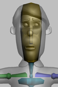
Pose
the head and feet:
- In
the Left viewport, rotate and scale the neck link so the biped’s chin
aligns with Wilson’s chin. Do not rotate the head.
- In
the Front viewport, scale the head to about half the width of Wilson’s
head, and to its full height.
- In
the Top viewport, rotate the biped’s feet to match the angle of
Wilson’s feet.
- In
the User and Left viewports, scale the foot and toe bones to represent
the bulk of the shoe and the toe portion of the shoe. If you have difficulty
selecting the toe bone, select the foot and press Page Down.
Complete
the posing process:
- As
necessary, scale biped parts so they are about two-thirds the width
of the mesh.
Wilson's pose is now complete.
- Select
the entire biped, and create a named selection set called Wilson
Biped.
TipIt’s
best to wait until you’ve finished posing the biped to make a biped
selection set. If you change parameters on the Structure rollout
and add more parts while you’re posing, any parts added in this
way will not be part of a selection set made at the start of the
posing process.
- In
the Biped rollout, click the expansion bar to display the Name field.
- Enter Wilson
Biped in the Name field.
All biped
parts are now preceded by the words Wilson Biped.
Naming the biped in this way greatly assists the process of merging
characters into scenes with multiple bipeds.
TipGiving
each of your bipeds a unique name is a good practice. For example,
if you decide to merge the character into a scene that contains other
bipeds, the merge process won't ask you about duplicate names, and you'll
be able to tell them apart easily when selecting objects.
Save
the pose:
- Choose
the named selection set Wilson Mesh, and click Yes on
the warning dialog.
- On
the Display panel, turn off See-Through.
- Save
the scene to the file my_wilson_pose.max.
A finished
version of the pose can be found in the file align_wilson_complete.max.


 You
can quickly select the COM by clicking any of the selection buttons
in the Track Selection rollout: Body Horizontal, Body Vertical,
or Body Rotation.
You
can quickly select the COM by clicking any of the selection buttons
in the Track Selection rollout: Body Horizontal, Body Vertical,
or Body Rotation.