Mapping the Helmet

Mapping a Character

Vertex Color and Interactive Shading

Mapping the Pants
In
this lesson, you use the Unwrap UVW modifier to map the pants of
the helicopter pilot using a camouflage pattern. The pants would
be difficult to map using conventional mapping methods, especially
when you use a pattern like camouflage, without getting smearing
and stretching of pixels. Using multiple planar and cylindrical
maps might work to keep the pattern equal but may give you problems
with stitching. It is best to use Pelt Mapping in such a situation.
An added constraint is the belt, which is part
of the pants object. Since the belt will be using a different material
than the rest of the pants, you need to apply a Multi/Sub-Object
Material and map the two elements differently, using pelt mapping
for the pants and a simpler cylindrical mapping for the belt.
Adjust
material IDs:
- Continue
working on your file from the previous exercise or load the file pilot03.max found under \tutorials\unwrap_uvw.
- Zoom
in on the pilot’s pants in all viewports.
-
 Select
the Pants object and go to the Modify
panel.
Select
the Pants object and go to the Modify
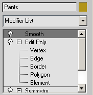
panel. - Expand
the Edit Poly modifier in the stack and go to Polygon sub-object
level.
- Activate
the Front viewport then press Ctrl+A to
select all the faces that make up the pants object (pants + belt).
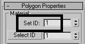
- Scroll
down to the Polygon Properties rollout at the bottom of the Modify
panel. Set the Set ID value to 1.
This sets all the faces to be applied with the
first material in a multi/sub-object material definition.
-
 Using
a window selection, drag to select all the faces that make the belt.
Using
a window selection, drag to select all the faces that make the belt.
- On
the Polygon Properties rollout, set the Set ID value to 2.
The faces representing the belt will receive
the second material in a multi/sub-object material definition.
- Click
an empty area of the viewport to deselect all polygons.
- Exit
Sub-object selection level, and then go to the top of the stack
by clicking the Smooth modifier entry.
Apply
the material to the pants:
- In
the Perspective viewport, zoom in on the pilot’s pants.
- Press M to open the Material Editor.
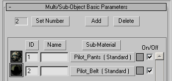
- Find
the material named Pilot_Pants and select it.
This is a Multi/Sub-Object material with two
defined sub-materials.
- Drag
this material to on the pants in the Perspective viewport.
- Close
the Material Editor.
Create
pelt seams:
When you use Pelt mapping, it is best to start
by defining pelt seams. Pelt seams are like virtual “cut” lines
that the UVW Map modifier uses to unfold the Pelt map.
-
Select
the Pants object then go to the Modify
panel.
- From
the Modifier list, choose Unwrap UVW.
- Maximize
the Perspective view and press F4 to
turn Edged Faces mode on if it is not on already.
- Press F3 to display the view in wireframe.
- Expand
the Unwrap UVW modifier and in the modifier stack, go to Edge sub-object
level.
- On
the Parameters rollout > Display group, turn off Show Map Seam.
The green map seams will make the blue Pelt seams difficult to see.
- Select
the vertical edge at the back center of the belt.
- On
the Selection Parameters rollout, click the Loop button.
The edges are now selected in a loop from the
back to the front passing between the legs.
At this point, you can convert this edge selection
to a Pelt Seam, but you really only need the selected edges at the
back of the pants. You can deselect the edges you do not want or
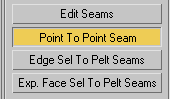
use a different approach called Point To Point Seam.
- Click
a blank area of the viewport to deselect the edges. At the very
bottom of the command panel, click the Point To Point Seam button.
- Click
a point on the belt where you want the pelt seam to start.
- Arc
Rotate to view the pants from a lower angle and click a point in
the middle between the pants legs.
- Right-click
to accept the seam. You now have a pelt seam running along the buttocks.
- Repeat
the Point To Point procedure to create a pelt seam running along
the inside of a leg.
- Create
a pelt seam for the inside of the other leg.
- Press F3 to restore the view to shaded mode.
- In
the modifier stack, set the sub-object level to Face.
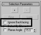
- On
the Selection Parameters rollout, turn off Ignore Backfacing.
- Press Ctrl+A to select all the faces that
make up the pants.
They turn red in the viewport.
- On
the Map Parameters rollout, click the Pelt button.
A planar mapping gizmo appears in the viewport.
- Click
the Align Y button to align the gizmo with the world XZ plane (that
is, perpendicular to the Y axis).
- At
the bottom of the rollout, click the Edit Pelt Map button.
The Edit UVWs dialog appears along with the
Pelt Map Parameters dialog.
NoteThe
display of the geometry in the Edit UVWs dialog is slightly different
from what you have seen so far. A circular Stretcher is displayed.
you'll use this to simulate Pelt mapping by stretching the geometry. You
need to adjust it slightly so that it works properly.
- From
the Maps drop-down, choose the map that was defined in the Multi/Sub-Object
material for the pants.
The camouflage texture appears in the background.
NoteBecause
the material applied to the pants is a Multi/Sub-Object material,
all maps used in the material definition are automatically displayed
in the map drop-down menu; in this case the camouflage and the belt map.
-
 On the
Edit UVWs main toolbar, choose the Scale tool.
On the
Edit UVWs main toolbar, choose the Scale tool. - Position
the cursor on one of the Stretcher control points. Scale the stretcher
up slightly until it reaches the boundaries of the camouflage map.
-
 On the
Edit UVWs toolbar, choose the Rotate tool.
On the
Edit UVWs toolbar, choose the Rotate tool. - Make
sure Angle snap is off. Position the cursor on one of the stretcher’s
control point, and rotate the stretcher to get a more symmetrical
layout.
- In
the Pelt Map Parameters floating dialog, click the Simulate Pelt
Pulling button.
The faces are stretched out based on the pelt
seams you created.
- Click
the Simulate Pelt Pulling button two more times for additional stretching.
The end results are getting better in the viewport,
but the mapping can be made better with a bit of “relaxing.”
- On
the Pelt Map Parameters floating dialog, click the Relax (Light)
button three times. Keep an eye on the viewport to compare the results.
Map
the belt:
Unlike the pants, the belt uses a simple cylindrical
mapping, much like the one you used on the helmet in the previous
exercise.
- In
the modifier stack, switch the Unwrap UVW sub-object level to Face.
- In
the Map Parameters rollout, click the Pelt button to exit this mode.
- Click
a blank area of the viewport to deselect the faces.
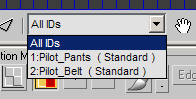
- On
the Edit UVWs dialog, open the face ID dropdown list.
- Choose
2:Pilot_Belt (Standard) from that list. Only the faces that make
out the belt are selected.
NoteThe
background automatically switches to reflect the map associated
with the faces that use that Material ID.
- In
the Edit UVWs window, drag to region-select all the faces representing
the belt.
The corresponding faces are selected in the
viewport.
- Press F3 to switch to wireframe display
mode.
- On
the Map Parameters rollout, click Cylindrical, then click Align
Z to align the cylindrical gizmo to the belt.
- Make
sure Angle Snap is on and rotate the gizmo 90 degrees on the Z axis
(blue axis) so that the green seam is at the back.
- On
the Map Parameters rollout, click the Fit button to fit the gizmo
to the belt.
- Click
the Cylindrical button to turn it off.
- At
the bottom-right corner of the Edit UVWs dialog, click the Options
button.
- In
the extended group that appears, set the Brightness value to 1 to
get a better view of the background.
-
 On the
Edit UVWs toolbar, click the Freeform mode tool.
On the
Edit UVWs toolbar, click the Freeform mode tool.
- Make
a preliminary adjustment using Scale (cursor on the corner control
points) and Move (cursor inside the selection) to position the selected
faces over the belt in the background image.
- Press F3 to return to shaded display mode.
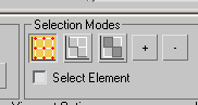
- On
the Edit UVWs dialog, switch the selection mode to Vertex.
- Select
all the bottom vertices on the belt line.
-
 From
the Edit UVWs window’s main toolbar, open the Scale flyout and choose
the Scale Vertical tool.
From
the Edit UVWs window’s main toolbar, open the Scale flyout and choose
the Scale Vertical tool. - Place
your cursor on one of the selected vertices then click and drag
down to straighten the belt line.
- Select
the upper belt line and straighten it as well.
- Select
the vertices around the buckle.
-
 Using
Scale Horizontal and Move, adjust the vertices to get a better-looking
buckle in the viewport.
Using
Scale Horizontal and Move, adjust the vertices to get a better-looking
buckle in the viewport.
- Close
the Edit UVWs dialog when done.
- In
the modifier stack, exit the sub-object level.
- Save
your file as my_pilot_pants.max.
Summary
This tutorial has introduced you to several
mapping methods using the Unwrap UVW modifier. You have used simple
mapping techniques such as planar and cylindrical, as well as more
elaborate techniques such as pelt mapping to seamlessly wrap textures
around objects. These tools can be adapted to the task of mapping
any object in 3ds Max.
.png)
.png)
.png)
.png)
.png)
.png)
.png)
.png)
.png)
.png)
.png)
.png)
.png)
.png)
.png)
.png)
.png)
.png)
.png)