Mapping the Shirt

Mapping a Character

Mapping the Pants

Mapping the Helmet
In this lesson, you use the Unwrap UVW modifier to
map the helmet of the helicopter pilot. Unlike the shirt, the helmet
cannot be easily mapped with a Planar projection. You will use a
cylindrical projection instead.
Apply
the material to the helmet:
- Continue
working on your file from the previous exercise or load the file pilot02.max found under \tutorials\unwrap_uvw.
- Zoom
in on the pilot’s helmet in the Perspective viewport.
- Press M to open the Material Editor.
- Find
the material named Pilot_Head. Drag this material
and drop it on the helmet in the Perspective view.
- Close
the Material Editor.
Map
the helmet:
-
 Select
the Helmet, then go to the Modify panel.
 - From
the Modifier list, choose Unwrap UVW.
- Expand
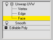
the Unwrap UVW modifier, then choose Face sub-object level.
- On
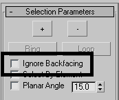
the Selection Parameters rollout, turn off Ignore Backfacing.
- Drag
to region-select all the faces that make the helmet. The whole helmet
turns red.
- On
the Map Parameters rollout, click the Cylindrical button. A cylindrical
mapping gizmo appears, but its size and orientation are incorrect.
- On
the Map Parameters rollout, click on Align Y to adjust the gizmo
to the helmet.
NoteTake a look at the vertical green edge at
the front of the cylindrical gizmo. This represents the edge that
will be used to unfold the map. You will need to rotate that edge
to the back of the helmet to better fit the map assigned to the
material.
- From
the main toolbar, click the Rotate tool and set Reference Coordinate
System to Local.
- Press
the A key to turn
on Angle Snap.
- In
the perspective view, rotate the gizmo 180 degrees on the Z axis
(blue axis) until the green edge is at the back of the head.
- On
the Parameters rollout, click Edit to open the Edit UVWs dialog.
The selected faces are unfolded against a checkered
pattern, but it might not be completely symmetrical.
- Rotate
the cylindrical gizmo an additional 5 degrees on the Z axis.
This fixes the selected faces into a perfectly
symmetrical layout.
- On
the Map Parameters rollout, click the Cylindrical button to exit
that mode.
- In
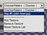
the editor, from the map drop-down list, choose the helmet map defined
in the material.
- Make
sure the Options button in the bottom right corner of the dialog
is active.
- In
the Bitmap Options group, set the Brightness to 1.0.
This makes the background image easier to read.
-
 On the
dialog’s main toolbar, make sure the Freeform Mode tool is selected.
 - Position
the cursor on one of the corner boxes to scale the selected faces,
or anywhere inside the selection to move the selected faces.
- Make
a preliminary adjustment for the selected faces to fit the background
image.
- In
the Selection Modes group at the bottom of the dialog, choose Vertex
sub-object mode.
- Adjust
groups of vertices, as you did in the previous exercise.
- Exit
the Edit UVWs dialog when done. In the Modifier stack, exit the
sub-object level.
When you are done, save your file as my_pilot_helmet.max.
 Select
the Helmet, then go to the Modify panel.

.png)
.png)

.png)
.png)
.png)

 On the
dialog’s main toolbar, make sure the Freeform Mode tool is selected.
On the
dialog’s main toolbar, make sure the Freeform Mode tool is selected..png)

.png)