


Autodesk 3ds Max Tutorials > Materials and Mapping Tutorials > Introduction to Materials and Mapping >
Mapping and Mapping Coordinates
Adding images and textures to a material is one of the most important techniques for creating realistic effects. In this lesson, you learn how to add texture maps and bump maps to a material. You also learn how to position a map on the surface of an object by adjusting the mapping coordinates of the material.
Make a texture map:
Suppose you want to make a realistic orange in your scene. The most direct way is to use a realistic image as the texture map in the diffuse component of a material. In other words, you replace the overall color with an overall texture. Here are the basic steps:
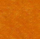
A cropped photograph of a real orange peel
Add a texture map to a material:
The digitized bitmap you are going to use is already being used by the orange material in the first sample slot. You can therefore browse for the bitmap from the Material Editor.
 Click
View Small Icons.
Click
View Small Icons.All the images that are currently loaded appear as small thumbnails.

 Click
View Large Icons.
Click
View Large Icons.The thumbnails appear larger.
The Material/Map Browser closes and the orange texture map appears in the material sample, but not in the viewport.
 To display
the texture map in the viewport, click the Show Map In Viewport
on the Material Editor toolbar.
To display
the texture map in the viewport, click the Show Map In Viewport
on the Material Editor toolbar.The orange texture map appears in the viewport.
Note on Mapping Coordinates and Viewport Visibility
The orange map shows in the viewport because the orange object has mapping coordinates applied to it. Like other parametric objects in 3ds Max, the sphere of the orange generated its own mapping coordinates when created. This is not necessarily the case with editable meshes and many other types of geometry.
If the object in the scene didn't have mapping coordinates, the map wouldn't appear in the viewport, even if Show Map In Viewport is on. In that case, you can add a UVW Map modifier to the object to make the texture display.
If the texture map still doesn't display, you can move the gizmo of the UVW Map modifier, and experiment with the Offset, Tiling, and Angle parameters in the Coordinates rollout. This will be covered later in the tutorial.
Add a bump map:
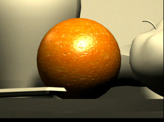
The texture on the orange looks all right, but a real orange peel has a pitted surface. You can simulate this and add realism by using bump mapping. This won't show up in the viewport, but is visible when you render.
 Click
Go To Parent to access the material level.
Click
Go To Parent to access the material level.There is no change in the viewport.
To really see the effect, you'll need to render the scene. It would also be a good idea to zoom in and see what's happening to the orange.
Nothing will change in the viewport, but this will let you use the experimental material for other purposes later in this exercise.
Use mapping coordinates and tiling:
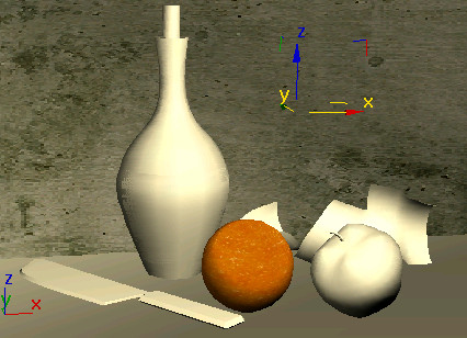
In this procedure, you use the concrete wall behind the objects to learn about mapping and tiling.
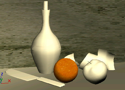
The concrete shows up in the camera viewport because the parametric object has generated its own mapping coordinates. But the concrete doesn't look quite right on the wall.
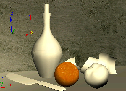
The concrete changes appearance in the viewport.
Choose the one that looks correct; probably Y.
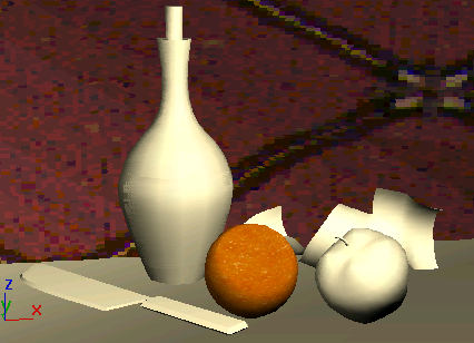
 On the
Main toolbar, turn on Select And Move. In the viewport, and drag
the gizmo for the mapping modifier to move the map.
On the
Main toolbar, turn on Select And Move. In the viewport, and drag
the gizmo for the mapping modifier to move the map.The concrete bitmap shifts behind the objects.
To control placement of texture maps:
To control tiling of texture maps:
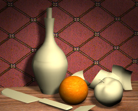
Create wallpaper with a tile pattern:
The rollouts change to the level of this map.
Turn
on Show Map in Viewport.A diamond pattern appears on the wall.
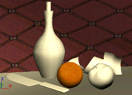
This makes the pattern proportions more even.

On some systems, the diamond pattern might be skewed in the Camera viewport. To correct this, right-click the Camera01 viewport label and choose Texture Correction.
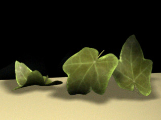
Use opacity mapping to make a leaf:
You can use the leaf objects in the scene to experience a unique type of mapping. The leaf is created with a simple box mapped with a texture map and an opacity map.
The texture is a photo of a leaf.
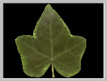
The opacity map is a mask of white and black. The black becomes transparent when rendered.
 On the
toolbar, open the Named Selection Sets list and choose the set named leavesandbase.
On the
toolbar, open the Named Selection Sets list and choose the set named leavesandbase. The leaves and the base are now the only objects visible.
This deselects the plank base.
The objects are really just thin boxes that have Bend and Twist modifiers applied to them. They don't look anything like leaves right now.
The leaf material is applied to all four leaves.

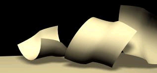
View the rendered leaves:
In this procedure, you zoom in without affecting your existing camera view.
The boxes seem to have been replaced by realistic leaves, and the opacity map and the shadow-casting spotlights combine to cast reasonable-looking shadows.
Use mapping coordinates:
Besides letting you see maps in the viewport, mapping coordinates give you control of how a texture is applied to the object. In this procedure, you'll add a UVW Map modifier to the bottle label. In the next procedure, you crop the texture.
Simple mapping is often solved by adding planar mapping coordinates and then working with the gizmo for adjustment. Let's see how this works on the label of the bottle.
 Open
the Modify panel and add a UVW Map modifier to the label.
Open
the Modify panel and add a UVW Map modifier to the label. Region
Zoom into the Front viewport so you have a better view of label01.
Region
Zoom into the Front viewport so you have a better view of label01.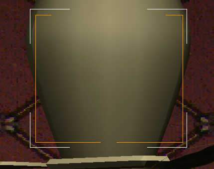
Region Fit lets you draw the gizmo to the size you want.
 Use
Assign Material To Selection to apply the material onto the label.
Use
Assign Material To Selection to apply the material onto the label.
Crop the texture:
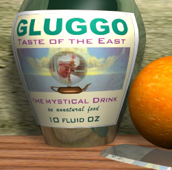
The Gluggo texture map doesn't really fit the label properly, so you'll fix it by using the cropping features of the Material Editor.
A Specify Cropping/Placement window is displayed showing the label bitmap.
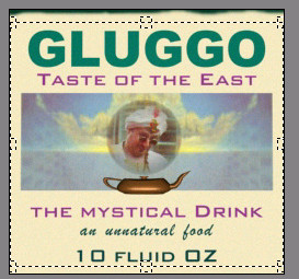
The dark edge no longer appears on the label in the viewport. Adjust the length and width of the modifier so that the map fits the label better.
Add a sticker on the label:

Set up the mapping modifier:
Everything disappears except for the label.
The label already has a UVW Mapping modifier applied to it.
The label changes orientation in the viewport.
Set up the label material:
Now the label map will use the mapping from the Gluggo label modifier, because they both use the same map channel.
Select faces:
Here, you'll select the faces where the Gulpco sticker will go.
 Turn
on Polygon selection.
Turn
on Polygon selection.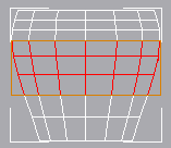
The label middle faces selected
This is an important step. If you don't turn off Polygon selection, what follows will not work as expected.
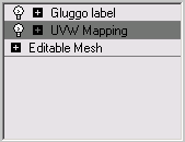
The new UVW Mapping modifier is inserted in the stack between the Gluggo label modifier and the Editable Mesh. It will supply the mapping coordinates for the Gulpco sticker.
Convert to a multi/sub-object material:
You'll use the original label as a base for the new label.
On the
Material Editor toolbar, click Go To Parent.Add a map to the second sub-material:
Click
Show Map In Viewport. The second map appears in the viewport, layered
on top of the first.
