This describes the GSM initial configuration of the DBS3900 GSM/UMTS for the BSC, which includes configurations of BTS attributes, logical TRXs, and cell attributes.
Prerequisites
- The data described in Data to Be Negotiated and Planned for DBS3900 Initial Configuration is already obtained.
- The BSC global data, BSC devices, BSC links, and BSC clock are configured.
- The GEIUB/GOIUB is configured. In addition, there are idle ports.
- The GXPUM is configured in the GMPS/GEPS where the GEHUB is located.
- The GDPUX is configured in the GMPS/GEPS where the GEHUB is located.
- Abis interface boards are classified into the GEIUB, GOIUB, GEHUB, GFGUB, and GOGUB.
- The RF modules of the GSM/UMTS BTS are classified into MRRU and MRFU. When the DBS3900 is applied, the MRRU is configured. When the BTS3900 or BTS3900A is applied, the MRFU is configured.
Procedure
- Obtain the negotiated and planned data of the GSM/UMTS base station and the data prepared for the RF channel allocator.
- Allocate RF channels through the RF channel allocator.
- Start the Add Site wizard on the BSC6000 Local Maintenance Terminal.
If...
Then...
A site is added for the first time,
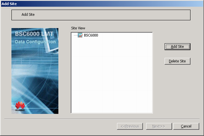
Right-click the GEHUB interface board of the GMPS or GEPS, and then choose from the shortcut menu. A dialog box is displayed, as shown in Figure 1.
A cascaded BTS is to be added under an existing BTS,
Right-click the existing BTS on the management tree, and then choose from the shortcut menu. A dialog box is displayed, as shown in Figure 1.
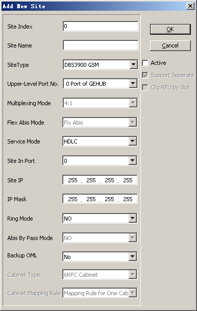
- Click Add Site. A dialog box is displayed, as shown in Figure 2. Then, set related parameters.
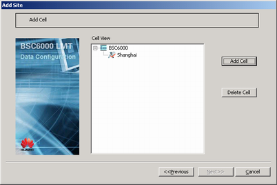
- Click OK. A dialog box is displayed, as shown in Figure 3.
- Click Next. A dialog box is displayed, as shown in Figure 4.
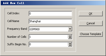
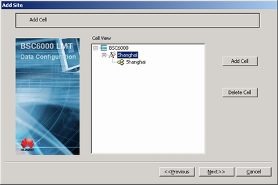
- Select the target BTS and click Add Cell. A dialog box is displayed, as shown in Figure 5. Then, set parameters in the displayed dialog box.
 CAUTION:
 If you find the configuration error of a frequency band in a cell or BTS after the configuration is complete, you need to delete the cell or BTS and then add a cell or BTS to modify the frequency band. The reason is that a frequency band cannot be modified in a configured cell or BTS.
- Click OK. A dialog box is displayed, as shown in Figure 6.
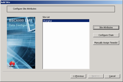
- Click Next. A dialog box is displayed, as shown in Figure 7.
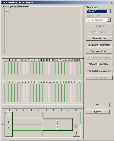
- Click Site Attributes. A dialog box is displayed, as shown in Figure 8.
- In the Site Device Attributes dialog box, right-click
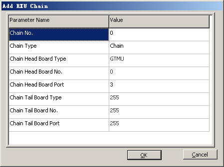
 and choose from the shortcut menu. A dialog box is displayed, as shown in Figure 9. Then set related parameters.
 NOTE:
NOTE: - Chain Head Board Port must be set to 3, 4, or 5. Among six CPRI ports on the GTMU, ports 3, 4, and 5 are used to connect the RF module; ports 0, 1, and 2 are used to connect the three CPRI ports on the WBBP.
- Each GTMU supports a maximum of six RXU chains.
- When star and chain topologies are applied for the BBU and the RF module, each chain supports three-level cascading of the RF module.
- Chain No. is an identifier rather than the actual CPRI port number. The actual port number is specified by Chain Head Board Port.
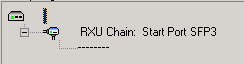
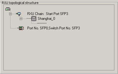
- Click OK. The RXU chain is added, as shown in Figure 10.
- Add the RF module. Right-click the RXU chain, and then choose . A dialog box is displayed, as shown in Figure 11. Then, set
related parameters.
NOTE:
RXU NAME of different RF modules under the same BTS must be unique. Otherwise, the system may display error information.
- Click OK. The RF module is added.
- Right-click an RF module, and then choose from the shortcut menu. The Basic Attributes of Site Board dialog box is displayed.
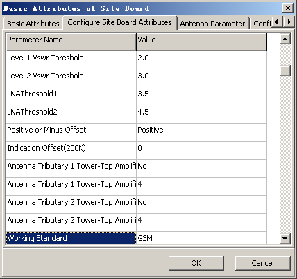
- In the dialog box, click the Configure Site Board Attributes dialog box, as shown in Figure 12.
- Set Working Standard to GSM and UMTS, and set other parameters.
Table 1 Description of setting board attributes of the BTS Parameter
Setting Description
Send Receive Mode
Set this parameter according to the actual RF connections. For details, see Setting Antenna Attributes.
Antenna Tributary 1 Tower-Top Amplifier Flag and Antenna Tributary 2 Tower-Top Amplifier Flag
Set this parameter according to the actual configuration of the antenna.
Antenna Tributary 1 Tower-Top Amplifier Attenuation Factor(dB) and Antenna Tributary 2 Tower-Top Amplifier Attenuation Factor(dB)
Set this parameter to TMA Gain-4. Obtain information on the "TMA gain" from the product specifications.
- Click OK to return to the Site Device Attributes dialog box.
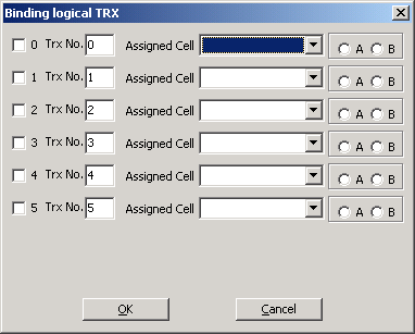
- Right-click an RF module, and then choose from the shortcut menu. A dialog box is displayed, as shown in Figure 13. Then, set related parameters.
NOTE:
- In single TX channel mode, the total number of carriers (number of GSM carriers + number of UMTS carriers) is less than or equal to six; the total number of UMTS carriers is less than or equal to two; the total number of GSM carriers is less than or equal to six.
- In double TX channel mode, the carrier combination with non-transmit diversity that serves channels in different working modes should follow the following principles.
- The total number of carriers on each channel is less than or equal to four.
- The total number of UMTS carriers on each channel is less than or equal to two.
- The total number of GSM and UMTS carriers on two channels is less than or equal to six.
- Maximum total output power and number of TRXs
- For single channel A, the maximum total output power is 40 W and number of serving carriers ranges from 0 to 6.
- For channels A and B, the maximum total output power of each channel is 30 W, and number of serving carriers of each channel ranges from 1 to 4.
- Click OK to return to the Site Device Attributes dialog box.
- Repeat 13 through 20 to configure multiple RF modules and other logical TRXs.
NOTE:
For details about configuring the RXU chain and RF module in different cascading modes, see Adding the RXU Chain and RF Module (Star Topology), Adding the RXU Chain and RF Module (Chain Topology), or Adding the RXU Chain and RF Module (Ring Topology).
- Repeat 11 through 20 to configure multiple RXU chains.
- Add other modules to subrack 2 in the Site Device Attributes dialog box. For details, see Adding BTS Modules.
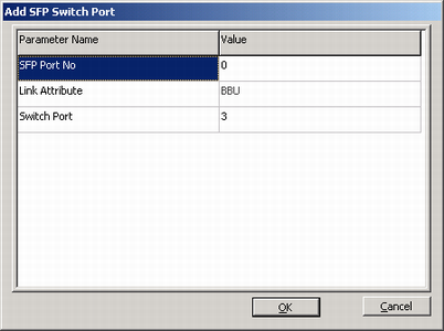
- Right-click and choose Add SFP Switch Port from the shortcut menu. A dialog box is displayed, as shown in Figure 14. Then, set parameters. For details about the mapping between the logical port SFP in the software and the physical port CPRI on the GTMU, see Table 2.
NOTE:
- The GTMU provides the SFP switching port for the WBBP. The data transfer between the WBBP and the RF module is implemented through the configuration of the switching port.
- SFP Port No specifies which port of the CPRI0, CPRI1, and CPRI2 of the GTMU connects to the CPRI port of the WBBP.
- Switch Port specifies which port of the CPRI3, CPRI4, and CPRI5 of the GTMU connects the RF module.
Table 2 Mapping between the SFP port and the CPRI port Physical Port on the GTMU
Logical Port
Connection Attributes
Switch Port
Description
CPRI_0
SFP_0
BBU
3-5
Physical port specifies a CPRI port that connects to the WBBP.
Logical port specifies a logical port that is bound to one of ports SFP_3, SFP_4, and SFP_5, thus achieving information exchange between the RF module and the WBBP.
CPRI_1
SFP_1
CPRI_2
SFP_2
- Click OK, as shown in Figure 15.
- If the GSM network needs to provide E1/T1 transmission timeslots to or borrow them from the UMTS network, set TOP switch parameters. For details, see Configuring the TOP Switching Parameters of 3900 Series BTSs.
- Click OK to return to the Add Site dialog box.
- Click Next. A dialog box is displayed, as shown in Figure 16.
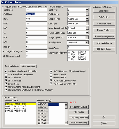
- Click Cell Attributes. A dialog box is displayed, as shown in Figure 17.
- Set parameters of basic cell attributes.
NOTE:
For two cells, the values of at least one of the following parameters should be different: MCC, MNC, LAC, and CI.
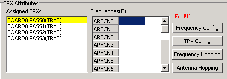
- In the TRX Attributes group box, select the allocated TRXs, as shown in Figure 18.
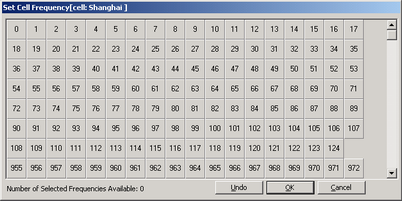
- Click Frequency Config. A dialog box is displayed, as shown in Figure 19. Then, select a frequency.
NOTE: Frequency spacing between carriers of each channel is described as follows:
- Frequency spacing between carriers in the UMTS network ranges from 4.2 MHz to 5 MHz.
- Minimum frequency spacing between carriers in the GSM network is 200 KHz.
- Frequency spacing between carriers in the GSM network and that in the UMTS network is 2.4 MHz.
- Click OK to return to the Set Cell Attributes dialog box.
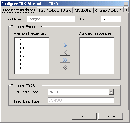
- Select the added cell, and then click Cell Attributes. A dialog box is displayed, as shown in Figure 20.
- Add a frequency corresponding to the TRX from Available Frequencies to Assigned Frequencies.
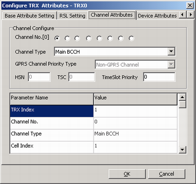
- Click the Channel Attributes tab. A tab page is displayed, as shown in Figure 21. Then, set the channel types corresponding to eight channel numbers.
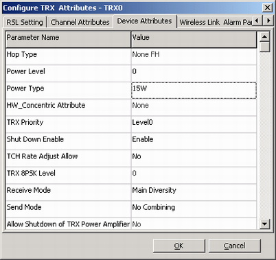
- Click the Device Attributes tab. A dialog box is displayed, as shown in Figure 22.
- Set Power Level, Power Type, Receive Mode, and Send Mode.
- Click OK to return to the Set Cell Attributes dialog box.
- Repeat 34 through 39 until the frequencies, channel attributes, and device attributes of all the TRXs in a cell are configured.
- Click OK to return to the Add Site dialog box.
- Repeat 29 through 41 until the attributes of all the cells are configured.
- Click Finish. The configuration of the BTS is complete.
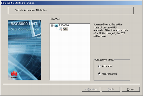
- Activating a BTS.
- On the Management Tree tab page of the BSC6000 Local Maintenance Terminal, right-click the target BTS and choose from the shortcut menu. A dialog box is displayed, as shown in Figure 23.