This describes how to add an SS7 signaling link on the A interface. This link is responsible for the signaling transmission between the BSC and the MSC.
| Scenario | BSC initial configuration and BSC capacity expansion |
| Mandatory/Optional | Mandatory |
- The SS7 signaling link can run at 64 kbit/s and 2 Mbit/s. The 2 Mbit/s signaling link can be 2.048 Mbit/s or N x 64 kbit/s (1<N<32). Only one rate type can be selected for one BM subrack.
- Each 2 Mbit/s signaling link can be configured with different bandwidths. The SS7 signaling links are in load sharing mode. Therefore, Huawei recommends that all the SS7 signaling links be configured with the same bandwidth. Each 2 Mbit/s signaling link can be the combination of any timeslots (except for timeslot 0) on an E1.
- One pair of signaling points can be configured with up to 16 SS7 signaling links.
- A minimum of two 2 Mbit/s signaling links must be configured between a pair of signaling points. Huawei recommends that these two signaling links be configured on different E1s/T1s or different STM-1s.
- Each GMPS or GEPS can be configured with up to thirty-two 64 kbit/s SS7 signaling links.
- Each GMPS or GEPS can be configured with up to eight 2 Mbit/s SS7 signaling links. In E1 transmission mode, the total bandwidth of all the links should not exceed 4 Mbit/s. In T1 transmission mode, the total bandwidth of all the links should not exceed 3 Mbit/s.
- The GEIUA/GOIUA board is already configured with other links of different type. You should reset the GEIUA/GOIUA if you need to configure this link.
- To improve the reliability of signaling links, on each Ater interface board (in the case of BM/TC separated mode) or A interface board (BM/TC combined mode), the total bandwidth cannot exceed 2M, and the number of signaling links cannot exceed two. It is recommended that the signaling links be distributed evenly on multiple interface boards.
Prerequisites
- The SS7 DPC is configured. For details, see Configuring the SS7 Signaling Points.
- The GXPUM is configured in the GMPS or GEPS that connects to the GTCS. The Ater connection path is configured. For details, see Configuring the GXPUM and Configuring the Ater Connection Path.
- The A interface E1/T1 is configured.
Preparation
- The following procedure takes how to configure a 64 kbit/s SS7 signaling link on the GEIUA in the GTCS as an example.
- For details about the configuration of the 2 Mbit/s signaling link, refer to Configuring High-Speed Signaling.
Parameter |
Example |
Source |
|---|---|---|
Ater Connection Path Index |
0 |
BSC internal planning |
BM Subrack No. of Ater Connection Path |
0 |
BSC internal planning |
Rate Type |
64 kbit/s |
Negotiation with the peer |
A Subrack No. |
7 |
BSC internal planning |
A Slot No. |
20 |
BSC internal planning |
A Port No. |
0 |
BSC internal planning |
Ater Timeslot Mask |
TS19 |
BSC internal planning |
A Interface Timeslot Mask |
TS16 |
Negotiation with the peer |
SLC |
1 |
Negotiation with the peer |
SLC Send |
1 |
Negotiation with the peer |
Procedure
- On the BSC6000 Local Maintenance Terminal, right-click GEIUA in the GTCS.
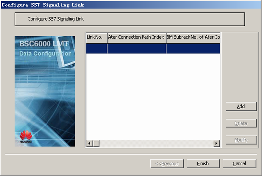
- Choose from the shortcut menu. A dialog box is displayed, as shown in Figure 1.
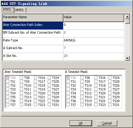
- Click Add. A dialog box is displayed, as shown in Figure 2.
- On the MTP2 tab page, set the parameters by referring to Table 1.
 NOTE:
NOTE: The number of timeslots on the A interface must be the same as that on the Ater interface.
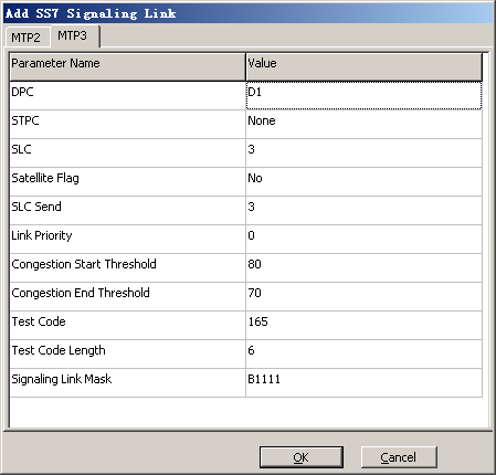
- Click the MTP3 tab. The tab page is displayed, as shown in Figure 3.
- Set the parameters by referring to Table 1.
- Click OK to return to the dialog box, as shown in Figure 1.
- Click Finish. The addition of the SS7 signaling link is complete.


