This describes how to configure the E1/T1 on the Pb interface to establish the physical path between the BSC and the PCU.
| Scenario | BSC initial configuration and BSC capacity expansion |
| Mandatory/Optional | Optional. A Pb interface E1/T1 must be configured when the BSC is configured with an external PCU. |
Prerequisites
- The PCU is configured. For details, see Adding a PCU.
- The GEIUP/GOIUP is configured. For details, see Configuring the GEIUP/GOIUP.
Preparation
Parameter |
Example |
Source |
|---|---|---|
Subrack No. |
0 |
BSC internal planning |
Slot No. |
22 |
BSC internal planning |
Port No. |
0 |
Negotiation with the peer |
Transmission Mode |
Terrestrial Transmission |
Negotiation with the peer |
Start PCIC |
0 |
BSC internal planning |
PCU No. |
1 |
BSC internal planning |
Procedure
- On the BSC6000 Local Maintenance Terminal, right-click GEIUP in the GMPS.
 NOTE:
NOTE: The configuration of the Pb interface E1 can be started only on the GEIUP/GOIUP in the GMPS or GEPS.
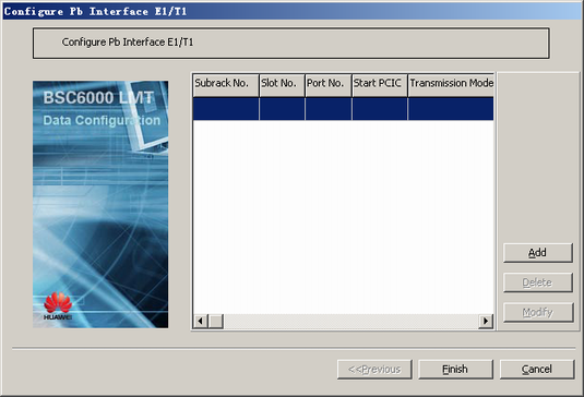
- Choose from the shortcut menu. A dialog box is displayed, as shown in Figure 1.
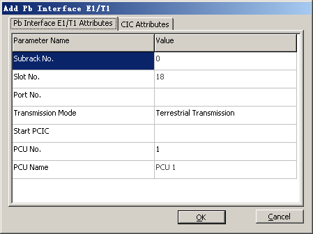
- Click Add. A dialog box is displayed, as shown in Figure 2.
- On the Pb Interface E1/T1 Attributes tab page, set the parameters by referring to Table 1.
 NOTE:
NOTE: The start PCIC must be a multiple of 128.
On the CIC Attributes tab page, you can use the default settings or change them as required.
- Click OK to return to the dialog box, as shown in Figure 1.
- Click Finish. The addition of the Pb interface E1/T1 is complete.

