


Autodesk 3ds Max Tutorials > Character Animation Tutorials > Character Animation without Biped > Introduction to Character Rigging >
Using List Controllers
When you create any object, including bones, default controllers are placed on the object to control its position, rotation, and scale.
For each transform, you can change the default controller to a list controller. This type of controller allows you to assign two or more controllers to the transform. The controllers are evaluated from first to last, and their values are added up to give the final transform value.
When you assign a list controller to a transform, the first controller on the list takes on the transform's current XYZ values, and the next controller starts off with a value of [0,0,0]. Then you can make the second controller active, so any animation will change the second controller's values only.
By assigning a list controller to the objects in your scene, you effectively set their animation transforms to [0,0,0] on the second controller regardless of how much you have moved, rotated or scaled the objects up to that point. If you wire parameters between two objects on the second controller, the transform values will match, and one object's parameters will predictably affect the other object's parameters.
In the case of a character rig, you have probably rotated the bones and controls to fit them to the character. Wiring the rotation of these objects to one another without using a list controller will cause one object to take on the posed rotation of another. For example, if you previously rotated a control shape by 90 degrees on the X axis to make it fit the rig, then you wire the control shape's X rotation to a bone's X rotation, the bone will suddenly rotate by 90 degrees to match the wired parameter. In such a case, you can use list controllers to cause both objects to start from a 0 rotation, and ensure that the control object will predictably affect the bone.
This lesson illustrates how you can use list controllers in a character rig.
Prepare the scene:
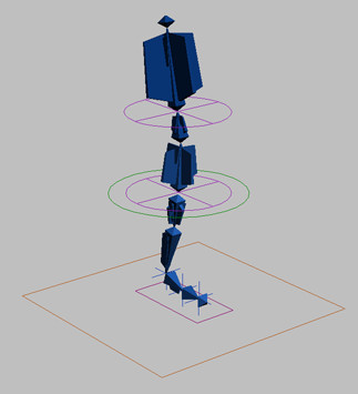
Right now, the control object CtrlSpine at the bottom of the spine can be used to rotate the character's entire spine. But when you twist your spine, your upper body rotates more than the lower part. You will simulate this motion by causing the upper spine bone, BoneSpine02, to rotate 1.5 times as much as CtrlSpine and BoneSpine01.
To achieve this, you will wire the rotation of BoneSpine02 directly to CtrlSpine. When you rotate CtrlSpine, BoneSpine02 will rotate by the same amount due to its linkage to BoneSpine01 and an additional half of the rotation due to the wiring.
Align the pivot points:
Before you can wire BoneSpine02 to CtrlSpine, you must make sure their pivot points are aligned. Later, when you wire each rotation axis of BoneSpine02 to CtrlSpine, you will know that the rotation axes match.
 On the
Hierarchy panel > Pivot > Adjust Pivot > Move/Rotate/Scale
group, turn on Affect Pivot Only.
On the
Hierarchy panel > Pivot > Adjust Pivot > Move/Rotate/Scale
group, turn on Affect Pivot Only. Use
Align to align the CtrlSpine pivot point with the
pivot point of BoneSpine02. On the Align dialog,
choose Pivot Point for both the Current Object and Target Object.
Use
Align to align the CtrlSpine pivot point with the
pivot point of BoneSpine02. On the Align dialog,
choose Pivot Point for both the Current Object and Target Object.Assign a rotation list controller:
Now you will assign a Rotation List controller to CtrlSpine's Rotation track.
 With CtrlSpine selected,
go to the Motion panel.
With CtrlSpine selected,
go to the Motion panel.Currently, the rotation track holds the default rotation controller, Euler XYZ.
 On the
Assign Controller rollout, click the Assign Controller button. Choose
Rotation List from the list of controllers, and click OK.
On the
Assign Controller rollout, click the Assign Controller button. Choose
Rotation List from the list of controllers, and click OK.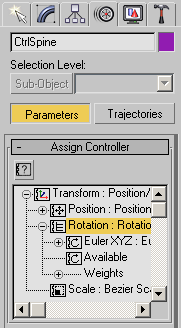
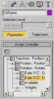
The Rotation controller branch now contains three items: Euler XYZ, Available, and Weights. The Euler XYZ controller is the controller that was previously on the Rotation track, and it holds any rotation applied to the object up to this point. The Available controller is a placeholder for any controllers you want to add to the list.
Click
Assign Controller. Choose Euler XYZ from the list of controllers,
and click OK.The Rotation List controller now shows two Euler XYZ controllers.
Name the controllers:
When you wire the second controller later on, your work will be much easier if you give each of the controllers a unique name now.
The name of the first Euler XYZ in the Layer listings changes to reflect this new name. This controller holds the initial rotation for the object.
This is the controller you will use for wiring.
When a controller is active, a small arrow appears to its left in the Layer listing. You will need to have the Wiring controller active when you animate the scene.
Assign a list controller to the spine bone:
You can find a version of this scene in the file tut_introrig_controllers.max.
Wire the controllers together:
Now you can wire together the rotation axes on each object's Wiring controller.
This will add half of CtrlSpine's rotation to BoneSpine02 on the X axis.
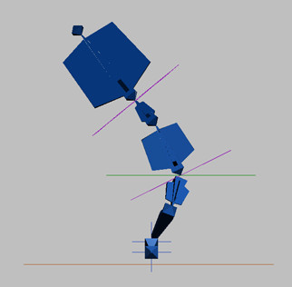
Test the wiring:
The lowest spine bone rotates by the same amount, but BoneSpine02, the higher spine bone, rotates a little more.
The animation on CtrlSpine was lost when you assigned the list controller. The character is out of balance on this frame.
You can find a version of this scene in the file tut_introrig_spinebend.max.