


Autodesk 3ds Max Tutorials > Character Animation Tutorials > Character Animation without Biped > Introduction to Character Rigging >
Wiring a Custom Attribute
In this lesson, you will create custom attributes to control the foot. A custom attribute is a parameter you create yourself.
The parameter doesn't control anything until you connect it to another parameter in the scene. You will use parameter wiring to connect the custom attributes to the rotation of the foot's IK chains.
Prepare the scene:
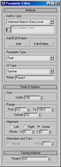
Create custom attributes:
The Parameter Editor dialog appears.
Determine the rotation axis to be wired:
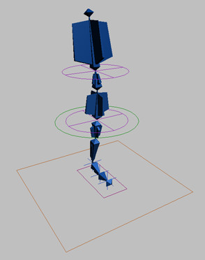
You want the new Roll parameter to rotate the IK chain at the ball of the foot so the character's heel will rise. In order to do this, you must find out which of the IK chain's axes of rotation should be affected by the parameter.
 On the
main Toolbar, turn on Select and Rotate.
On the
main Toolbar, turn on Select and Rotate.You can easily see which axis is affected by watching the display of numbers above the rotation gizmo. The X axis value changes as you rotate IKBall.
Wire the custom attribute to the IK chain's rotation:
Now you are ready to wire the Roll parameter to IKBall's X rotation.
When you wire parameters, the wiring is limited to the time segment that was active when the wiring was set. You can change this setting in Track View later on, but it is much easier to set the maximum time segment you think you might need before wiring. In this case, you will change the active time segment to 1000 frames.
 Click
Time Configuration, and change the Length parameter to 1000.
Click
Time Configuration, and change the Length parameter to 1000.Now you will create custom attributes on CtrlFoot, the control object for the foot. This will allow you to roll the foot by changing parameters on the Modify panel when CtrlFoot is selected. The custom attribute will be called Roll, and will range from 0 to 60 degrees.
A pop-up menu appears, giving you a choice of all parameter paths that are available for wiring. In this case, there are only two, Transform and Object.
A dotted line appears, extending from CtrlFoot's pivot point to the cursor. The dotted line indicates that you should choose an object and parameter path for the second object in the wiring pair.
The Parameter Wiring dialog appears.
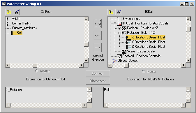
This dialog shows you the parameters that will be connected, and the direction in which the control will occur. In this case, you want the Roll parameter to affect the IK chain's X Rotation parameter.
This will cause Roll to control the X Rotation parameter.
The parameters are now wired together. Leave the Parameter Wiring dialog open as you test the wiring.
Test the wiring:
The foot spins wildly.
What is actually happening is a result of how 3ds Max handles rotations internally. You're probably familiar with degrees as a measurement of rotation. Ninety degrees is a quarter turn or rotation, 180 is half, and 360 is a full turn. However, many 3D applications use a different unit of measure called radians to measure rotations. Radians are based on the value of pi (approximately 3.1416).
With radians, 2 times pi is a full 360-degree spin. That is, 6.28 radians equals 360 degrees. Conversely, one radian is equal to about 57 degrees.
3ds Max comes with a built-in function, degtorad, that you can use to convert the Roll parameter to radians before passing it on to IKBall's X rotation.

This tells the wiring to use this expression for IKBall's X rotation.
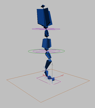
The heel comes up as you increase the Roll parameter, and stops rising when Roll reaches its maximum value of 60.
You can find a version of this scene in the file tut_introrig_toewiring.max.
Set up toe rotation:
You can use CtrlFoot to move or rotate the entire foot. However, if you tip CtrlFoot forward, it rotates from the center of the control shape. You can make it rotate from the toe tip by aligning its pivot point with IKToe.
 On the
Hierarchy panel, turn on Affect Pivot Only.
On the
Hierarchy panel, turn on Affect Pivot Only. Use
Align to align its pivot point with the pivot point of IKToe.
On the Align dialog, choose Pivot Point for both the Current Object
and Target Object, and choose the X, Y and Z axes.
Use
Align to align its pivot point with the pivot point of IKToe.
On the Align dialog, choose Pivot Point for both the Current Object
and Target Object, and choose the X, Y and Z axes.Now, when you rotate CtrlFoot, it rotates from the tip of the toe.
If you rotate CtrlFoot to test the setup, be sure to undo any rotation before continuing.
Wire the knee's swivel angle:
Now you will create and wire another custom attribute, this one for the knee's swivel angle.
This adds a KneeSwivel parameter to CtrlFoot.
Test the knee swivel:
The easiest way to see the KneeSwivel parameter in action is to look at the character with a bent knee. You can see this by going to frame 10, where the character is animated to bend its knee.
The knee swivels without affecting the foot.
Save the file:
You can find a version of this scene in the file tut_introrig_wired.max.