


Autodesk 3ds Max Tutorials > Character Animation Tutorials > Character Animation without Biped > Introduction to Character Rigging >
Setting Up IK Solvers
In order to manipulate the leg and foot interactively, you must apply an inverse kinematics solver (IK solver) to selected parts of the skeleton. An IK solver figures out (solves) how the bones should move or rotate based on a goal object. For example, you will place an IK solver on the leg with a goal at the ankle. When you move the goal, the ankle will move to the specified position, and the hip and knee bones will move and rotate accordingly.
There are several types of IK solvers in 3ds Max, each with a different purpose and usage. For rigging legs and arms, the HI solver is the most effective and easiest to use. It is designed to work with chains of two or more bones that bend in only one direction, such as knees and elbows. You will use this type of solver to rig the character's leg.
After you create the IK chains, you will look at their properties and parameters to gain an understanding of how they work.
Prepare the scene:
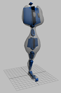
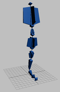
You do not need to see the mesh to set up IK solvers, and it will be easier to work with the bones if the mesh is hidden.
This leaves just the bones in the scene.
Create the ankle IK chain:
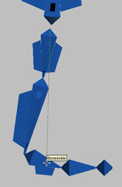
An IK solver assigned to a hierarchy of bones is called an IK chain. To create the IK chain for the leg, you start by selecting the highest bone in the hierarchy that will be part of the IK chain. Since you are creating an IK chain from the hip to the ankle, you will start by selecting the hip bone.
As you move the cursor, you will see a dotted line extending from BoneHip. Now you will choose the bone that defines the other end of the IK solver.
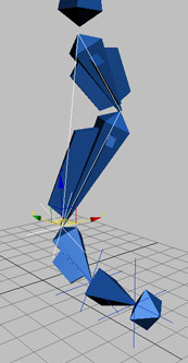
A set of cross hairs is created at the base of BoneAnkle, and a line appears between BoneHip and BoneAnkle. This is a visual representation of the IK chain.
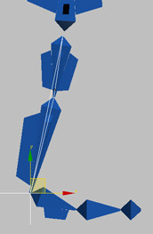
The cross hairs set the position of the IK goal. As you move goal, the knee bends to make the ankle reach the goal.
Rotating the IK goal around its own pivot point does not animate the bones in any way. In the next procedure, you will learn how to rotate the ankle so the heel lifts up.
Create the second IK chain:
If you want to rotate the ankle to raise the heel off the ground, you must rotate the IK goal around a point other than its own pivot point, such as the point between the foot and toe bones.
In animation of 3D objects, a common method for making one object rotate around another's pivot point is to link one object to another, then rotate the parent object. However, this approach will not work with an IK chain. If you link the IK goal to any of the bones with Select and Link, this will break the IK chain.
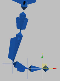
Instead, you will create an IK goal at the point between the foot and toe, and use this as the parent object to control the ankle IK goal's rotation.
The IK goal for this IK chain defines the ball of the foot.
 Use
Select And Link to link IKAnkle to IKBall.
Use
Select And Link to link IKAnkle to IKBall.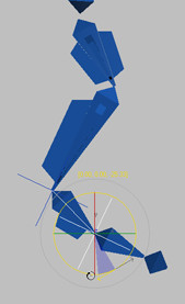
Now the ankle rotates, enabling you to make the heel rise up. However, the toe rotates downward as the heel goes up. You can force the toe to stay still by creating another IK chain that ends at the toe.
Create the third IK chain:
This will be the start of the third IK chain.
The ankle rises, but the toe stays still.
Link IKBall to IKToe.This rotates the entire foot. Undo any rotation before continuing.
You can find a scene with the IK chains in the file tut_introrig_ik.max.
Create a test animation:
As you have seen, rotating an IK chain itself has no effect on the bones. You have learned how to make an IK chain rotate around another point by linking it to another IK chain, and you have seen how you can use this to rotate the heel or entire foot upward.
However, the rotation of the linked IK chains does not affect the direction in which the knee points. The character rig will need to accommodate animation where the character swivels his hip to make the knee point in a different direction. To make this type of rotation, you will need to work with the IK chain's parameters. To see how this parameter works, you'll animate the IK chains to bend the knee. Working with a bent knee will enable you to see the hip swivel more easily.

Work with IK parameters:
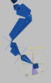
The first IK parameter you will work with is the swivel angle. This parameter determines how the bones in an IK chain will swivel (twist).
 Go to
the Motion panel.
Go to
the Motion panel.
When you change the swivel angle, the hip swivels to point the knee in another direction. The swivel angle is expressed in degrees, with 360 degrees making a full circle. This is the parameter you will use in the character rig to swivel the character's hip.
However, the foot bones also twist when you change the swivel angle, which is undesirable. You can prevent the foot bones from rotating by changing another IK parameter, the Parent Space. This setting is located on the IK Solver Properties rollout, just below the Swivel Angle parameter.
The Parent Space determines how the bones in an IK chain will twist when the IK chains are animated. By default, the bone's twist angle is determined by the twisting of its parent, the calf bone. When you change IKAnkle's swivel angle, the calf twists, and so does the ankle bone.
You can change the Parent Space setting so the foot bones don't inherit the calf bone's twisting. When you change an IK chain's Parent Space setting to IK Goal, the bones in the chain twist according to the animation on the IK goal, not the calf bone. This gives you more control over the foot, so you can make it rotate only when you want it to.
The ankle and toe bones are controlled by their own IK chains, so you will need to change the parameters for those IK chains.
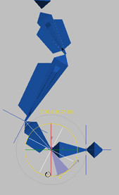
This time, the foot bones don't twist when the swivel angle changes.
Usually, the correct Swivel Angle value should be 0, 90, 180 or 270 degrees to correspond to the quarters of a 360-degree circle. You can also use a negative value such as -90 degrees, which is the equivalent of 270 degrees.
Set the swivel angle for the ankle and toe bones:
When you set the Parent Space to IK Goal for IKBall and IKToe, the ankle and toe bones might have rotated to an orientation other than its original setting. You can fix this by changing their swivel angles.
The IK chains on the leg should work properly now.
You can find a scene with correctly set swivel angles and parent space settings in the file tut_introrig_swivel.max.