Building the Spine


In this lesson, you'll use the Bones system along with the Spline IK feature to create the character's spine. Spline IK uses a spline shape to constrain a hierarchy along its length. This technique can be very useful for creating assemblies such as tails, snakes, or even hair.

If you are not familiar with the concept of IK solvers, see the lesson Setting Up IK Solvers in the Introduction to Character Rigging tutorial.

Prepare the scene:

  1. Open the scene you saved from the previous lesson, or open tut_char_bone_file02.max.

    Creating the spine will be easier if you first hide the leg bones. This will prevent the new spine bones from automatically appending to any existing bones.

  2. Select the leg bones. Right-click to display the quad menu, and choose Hide Selection.
  3. If necessary, click Min/Max Toggle to display four viewports.

    It will be easier to create the spine bones if you hide the grid and work in a shaded mode.

  4. With the Left viewport active, press the G key to turn off the grid.
  5. Change the Left viewport display to Smooth & Highlights.

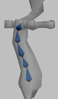
Create spine bones using spline IK:

Next you will create the spine bones, and you will apply a spline IK solver while you create the bones. Creating the spline IK solver at the same time you create the bones is easier than creating the bones alone, then applying the spline IK solver later.

  1. In the Create panel > Systems object type, click Bones to enter Bone creation mode.
  2. On the IK Chain Assignment rollout, choose SplineIK Solver from the IK Solver drop-down list.
  3. Turn on Assign to Children.
    NoteThe Assign To Children option assigns the specified IK solver to all newly created bones. Its accompanying option, Assign To Root, is active by default, and acts to assign the IK system to the root node of the selected hierarchy.
  4. In the Bone Parameters rollout > Bone Object group, set Width and Height to 5.0.

    Since you are creating several bones in a relatively confined space, a smaller bone size will help to make each bone more visible.

  5. In the Left viewport, create five or six bones starting at the hips and curving upward to the base of the neck, then right-click to end Bone creation mode.

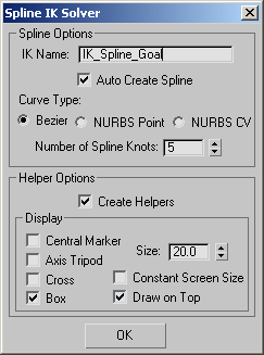
    The Spline IK Solver dialog appears with several options for spline creation. The controlling spline can either be a Bezier curve, a NURBS Point curve, or a NURBS CV curve. Depending on the particular application, each curve has its advantages. In this case, you'll use the default Bezier curve type.

  6. In the IK Name text field, change the name to IK_Spline_Goal.
  7. Set Number Of Spline Knots to 5.

    NoteThe number of spline knots doesn't have to coincide with the number of bones, although that is the default behavior. In this case, five knots are needed to provide sufficient spline control.
  8. Make sure that the Create Helpers option is enabled, and click OK.

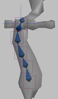
    The newly created bones are now constrained to the Spline IK shape. Five helper objects associated with the spline’s control knots have also been created. These helpers are used to control the spline shape and, hence, the spine hierarchy when the character is rigged.

    Next, you'll rename the newly created spine bones to match the previously established naming convention.

Rename the new objects:

  1. Select the spline on the spine, and rename it SplineIKSpline.
  2. Select all bones in the spine, but do not select the Spline IK shape, or any of the helper objects.
  3. Choose Tools menu > Rename Objects.
  4. In the Rename Objects dialog, turn on Base Name, and type BONE_Spine in the text field.
  5. Turn on Numbered, and set Base Number and Step to 1.
  6. Make sure all the other options are turned off, and click Rename.

    Now, you'll do the same for the spine helper objects. You'll use the same settings that were used for the spine bones, but change the base name.

  7. Select all of the helper objects.
  8. In the Rename Objects dialog, change the Base Name to HELPER_Spine.
  9. Make sure that all other options are configured as before, and click Rename.
  10. Close the Rename Objects dialog.

Change the coloring and add fins:

Next, you'll use Bone Tools to change the colors of the spine bones.

  1. Select all the bones in the spine.
  2. Choose Animation menu > Bone Tools.
  3. In the Bone Tools dialog > Bone Coloring group, apply a color gradient of your choosing to the selected bones.
  4. In the Fin Adjustment Tools rollout > Fins group, turn on Side Fins, Front Fin, and Back Fin, and set their Size values to 7.0, 3.0, and 7.0, respectively.
  5. Select the last bone (at the neck) and turn off all fins.

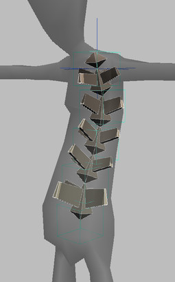
    Feel free to adjust each bone’s fin size and taper to your liking. Also, you can adjust each bone’s position relative to one another along the spline by clicking the Bone Edit Mode button and moving any spine bone.

    You can also unhide the leg bones if you want to check their relationship to the spine.

  6. Save your work as my_char_bone_spine.max.

    You can also open tut_char_bone_file03.max to examine the result of this lesson.

Next

Building the Arms