


Autodesk 3ds Max Tutorials > Character Animation Tutorials > Character Animation without Biped > Creating and Editing Character Bones >
Building the Leg Bones
In this lesson, you'll use the 3ds Max Bones to create a character’s leg bones.
If you have never created bones before, it is recommended that you do the lesson Creating a Bone Structure in the Introduction to Character Rigging tutorial before doing this lesson.
Prepare the scene:
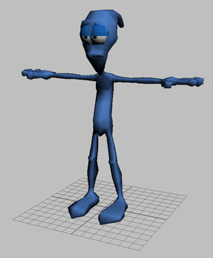
This character was built standing in what is known as a neutral or initial pose, with its arms outstretched and its feet planted a short distance apart. The initial pose is extremely practical for rigging and skinning a character.
The mesh turns grey and can no longer be selected by the cursor. This effectively gets the mesh out of the way, while maintaining its visibility for reference during bone creation and placement.
However, since you will be working predominately in a shaded view during the bone-creation lesson, it would also be helpful if you could partially see through the “solid” mesh. You will set the mesh object’s See-Through property to accomplish this.
Unfortunately, because the mesh is now frozen, it can no longer be selected. There are several methods to access an object’s properties in this case. The most obvious way is to unfreeze the object, set its applicable property, and refreeze it. Another way, however, is to set the object property directly using MAXScript. A third way, and the one you’re going to use, is to set the object property graphically using Schematic View.
 On the
Main toolbar, click Open Schematic View.
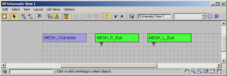
On the
Main toolbar, click Open Schematic View.Several items, or nodes, are displayed in the Schematic View window. One of the nodes is labeled MESH_Character; this is the frozen character mesh.
The character is now frozen and partially transparent. This will allows you to easily see the bones you create during this lesson.
Create the left leg bones:
In this lesson, you'll create a total of five bones to define the left leg: The upper and lower leg bones, a foot bone, a toe bone, and the toe tip bone.
 Click
Min/Max Toggle to display four viewports.
Click
Min/Max Toggle to display four viewports.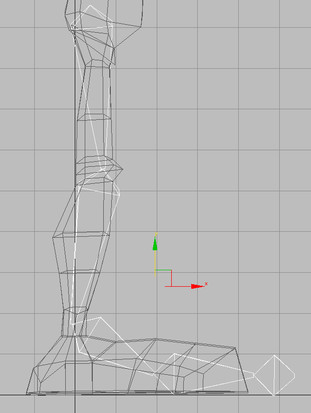
In the Perspective view, you’ll see that the five bones have actually been created directly between the mesh’s legs. This is because all objects are created on the current construction plane. The default construction plane consists of three interpenetrating planes that intersect at the world origin. The default grid in each view represents one of these planes; in the case of the Left view, the default grid is the YZ plane.

Now would be a good time to rename each bone for easier identification in future exercises. A good naming convention helps to organize the scene in a way that enables fast recall of scene components. There are no hard rules for object naming; the general rule of thumb is to consider that someone else, let alone yourself, should have easy access to any component of your scene with minimal browsing.
The L in the object name refers to the left leg.
Create the right leg bones:
You can take advantage of the time invested making the left leg bones by using the Mirror tool to construct the right leg bones quickly.
These two toolbar controls are known as transform managers. These settings determine the behavior of certain transform operations that depend on an object’s (or multiple objects’) pivot point. Use Pivot Point is the default center point for single selected objects, whereas Use Selection Center is the default for multiple selected objects.
Use Transform Coordinate Center places the center point at the origin of the specified reference coordinate system. In the case of the World coordinate system, this places the center squarely between the mesh’s legs.
You'll now use the Mirror tool to copy the left leg over to the right side.
 On the
Main toolbar, click Mirror Selected Objects.
On the
Main toolbar, click Mirror Selected Objects.You now have a perfect replica of the left leg bones at the correct position inside the mesh’s right leg.
Rename the right leg bones:
When you mirrored and copied the left leg bones to the right side, each bone name was appended with the number 01. Next, you’ll quickly rename the bones to reflect their switch to the right-hand side using the Rename Objects tool. This tool allows you to intelligently rename any number of selected objects at once.
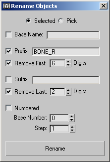
The name of each bone in the right leg has been changed to indicate that it is now on the right-hand side of the character mesh. In this case, the Rename Objects tool first removed the first six digits and the last two digits of each name (“BONE_L” and “01”).
Adjust the leg bone properties:
Now you'll use Bone Tools to change the appearance of the leg bones. These tools allow you to adjust the properties of any number of bones at one time. In this procedure, you'll use Bone Tools to add a different color gradient to each leg for easy differentiation, and to add fins to the foot and toe bones.
The left leg bones’ colors now range from light blue at the upper leg to dark blue at the toe tip.
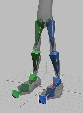
The different bone colors make it relatively easy to differentiate between the start and end joints, as well as between the left and right legs, even when viewed from a distance.
Now you'll add fins to the foot and toe bones.
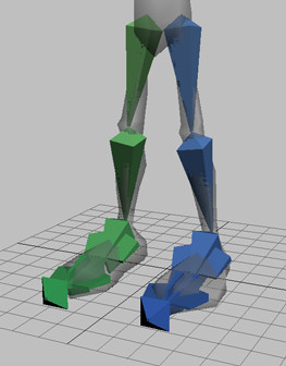
The foot and toe bones now fit more snugly within the boundaries of the character mesh. This will be pertinent when you skin the character in later lessons.
You can also open tut_char_bone_file02.max to examine the result of this lesson.